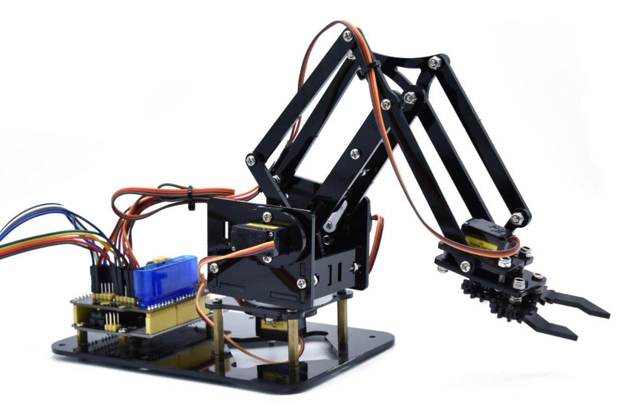
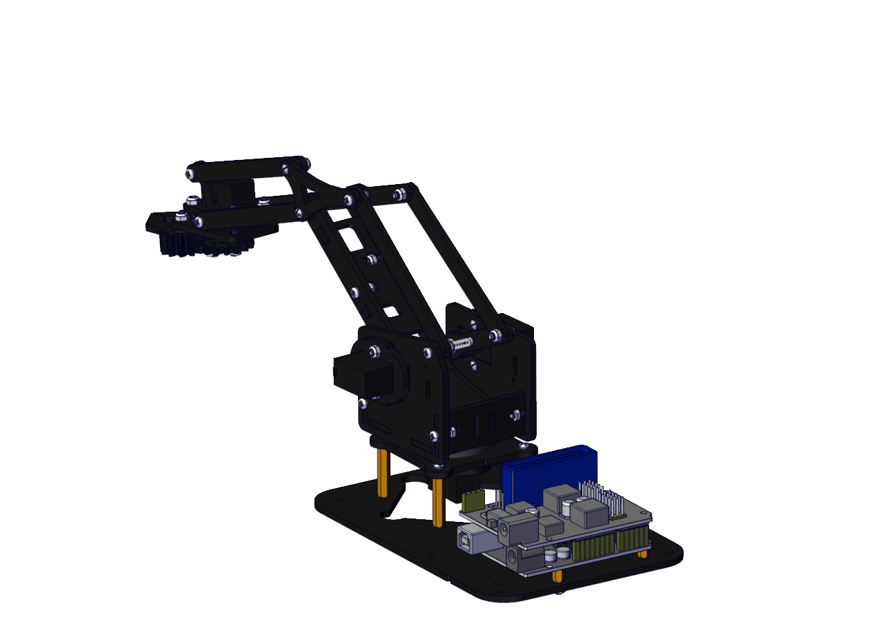
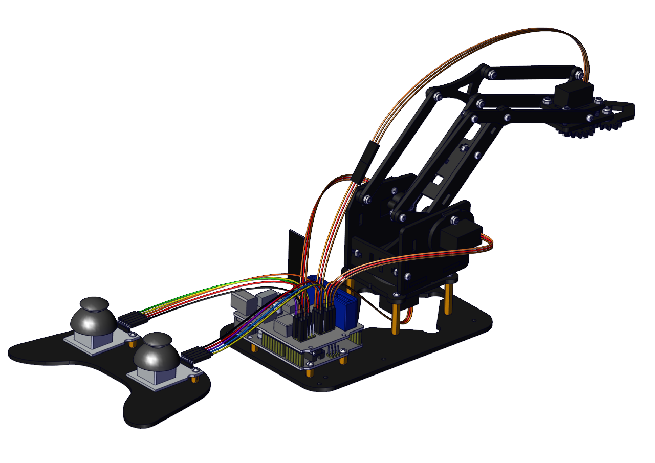
Keyestudio 4DOF Robot Arm Kit for Arduino DIY
Read me frist
Download the APP, Code and library from the link: https://fs.keyestudio.com/KS0198-X
1. Overview
DIY is the activity of making or repairing things yourself, especially in your home. Historically, it has been popular all over the world since 1960s, making our routine life interesting.Combined with STEM education, DIY products can greatly cultivate teenagers’ imagination and creativity.
Therefore, we Keyestudio R&D group rolls out an amazing 4DOF mechanical arm kit, which contributes to improving kids’hand-on ability, logical thinking and observation ability.
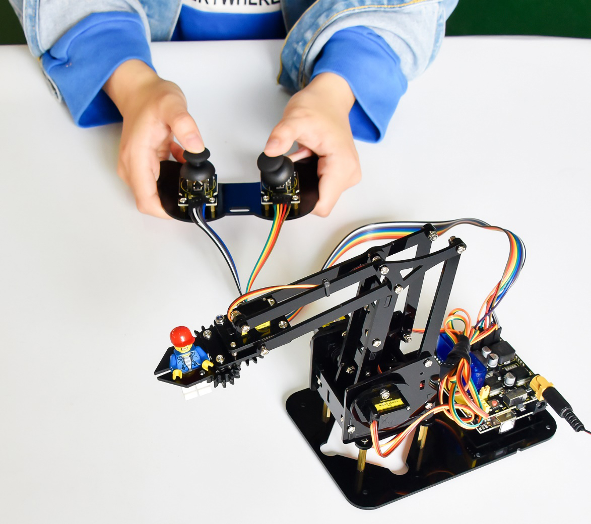
It is easy to build to say the least. In fact, the four servos of this robot arm are controlled by V4.0 control board and two joystick modules. What’s more, the detailed tutorials are provided for you even you are a starter.
For this mechanical robot arm, there are three methods to control. The first one is controller handle we provide(joystick modules), the second one is App; and the third one is wireless PS2 joystick module(not included in this kit).
I believe that you can’t help getting down with this kit.
Next, let’s get started.
2. Features
You can check out these features:
Detailed installation instructions
Detailed debugging methods, starting Arduino from entry.
Three controlling methods: Wired JoyStick Control; Phone Bluetooth Control; Wireless PS2 JoyStick Control.
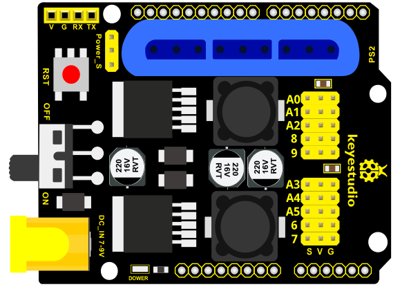
The parameters of keyestudio servo motor/ drive shield are as follows:
VIN voltage: VIN = DC 7-15V
VIN current: 5A
Two-channl 5V output: 5V/3A
PS2 interface: compatible with Sony PS2 receiver, can be plugged directly into the expansion board.
Dimensions: 73*53.34mm
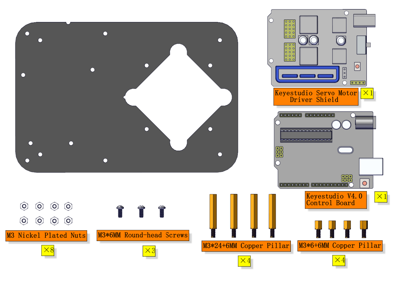
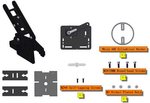
3. Kit List
You can see a pretty beautiful packaging box for the arm kit, and inside the packaging you will find all the parts and screws listed below.
Note: Peel the plastic film off the board first when you install robotic arm.
No. |
Item |
QTY |
Picture |
|---|---|---|---|
1 |
Keyestudio V4.0Control Board |
1 |
|
2 |
Keyestudio Servo Motor Driver Shield |
1 |
|
3 |
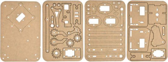
Acrylic Boards |
1 |
|
4 |
Acrylic Handle |
1 |
|
5 |
MeArm ABS Cylindrical Holder |
1 |
|
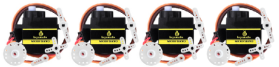
6 |
180° Black Servo |
4 |
|
7 |
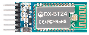
BT-24 Module |
1 |
|
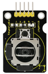
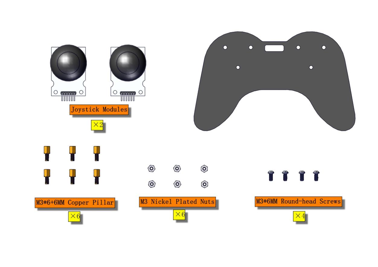
8 |
Keyestudio Joystick Module |
2 |
|
9 |
3D PS2 Joystick Cap |
2 |
|
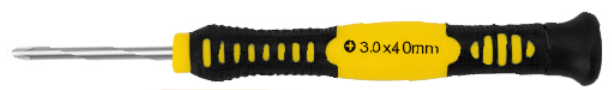
10 |
3*40MM Screwdriver |
1 |
|
11 |
Galvanized Wrench |
1 |
|
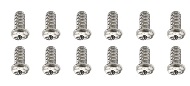
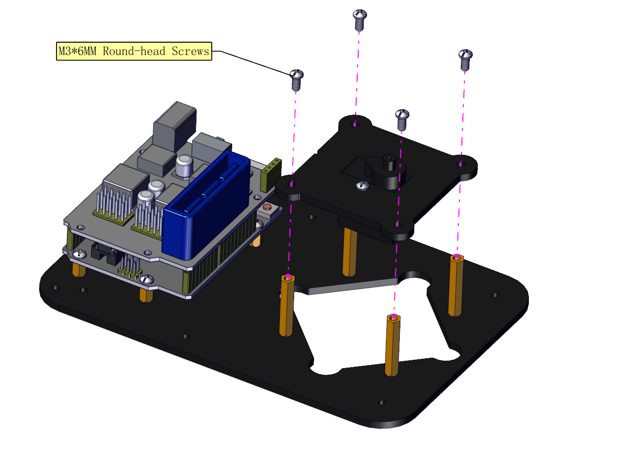
12 |
M3*6MM Round Head Screws |
12 |
|
13 |
M3*10MM Round Head Screws |
22 |
|
14 |
M3*14MM Flat Head Screws |
2 |
|
15 |
M3*12MM Round Head Screws |
12 |
|
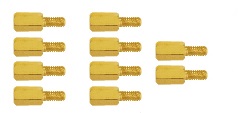
16 |
M3*24+6MM Copper Pillar |
4 |
|
17 |
M3*6mm+6mm Copper Pillar |
10 |
|
18 |
M3 Stainless Steel Hex Nuts |
22 |
|
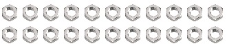
19 |
M3 Hexagon Nuts |
24 |
|
20 |
M1.2x5MM Phillips Self-tapping Screws |
8 |
|
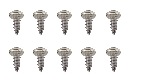
21 |
M2x5MM Phillips Self-tapping Screws |
10 |
|
22 |
M3 304 Stainless Steel Flat Washer |
10 |
|
23 |
M2x8MM Phillips Self-tapping Screws |
2 |
|
24 |
M3*16MM Flat Head Screws |
2 |
|
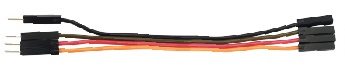
25 |
Male-Female 10CM Jumper Wire |
4 |
|
26 |
Female- Female 50CM Jumper Wire |
10 |
|
27 |
Black 3*100MM Cable Ties |
7 |
|
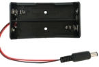
28 |
18650 2-Slot Battery Holder |
1 |
|


4. Assembly Guide
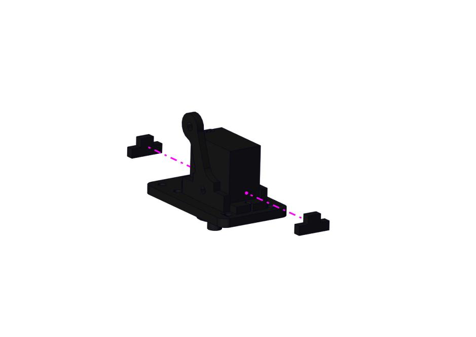
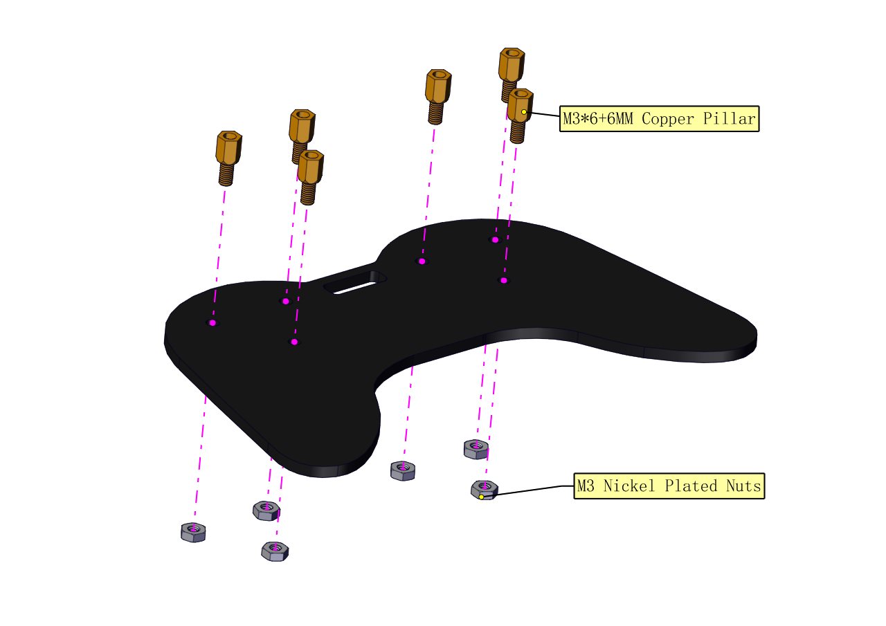
(1) Install the base of the robotic arm
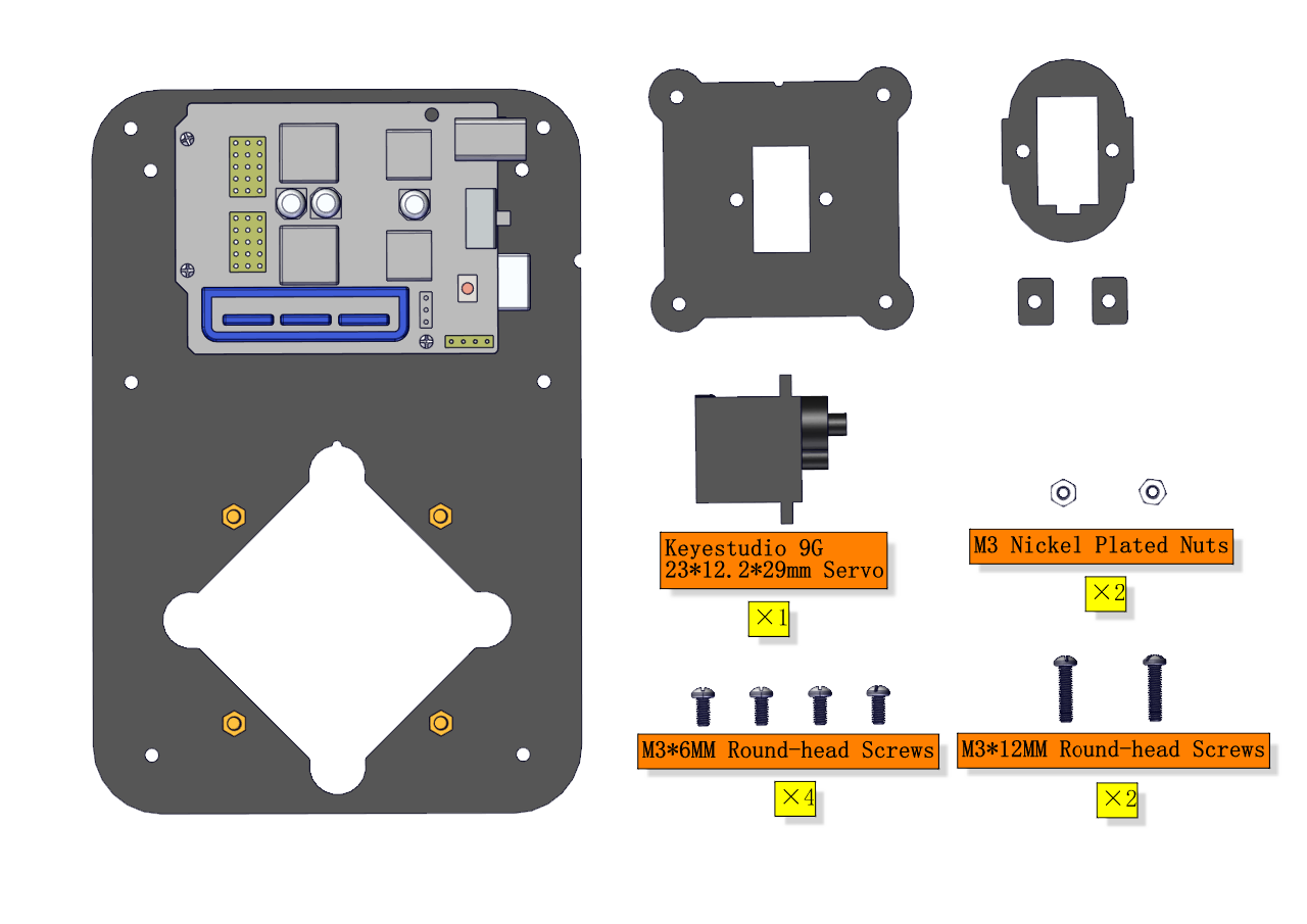
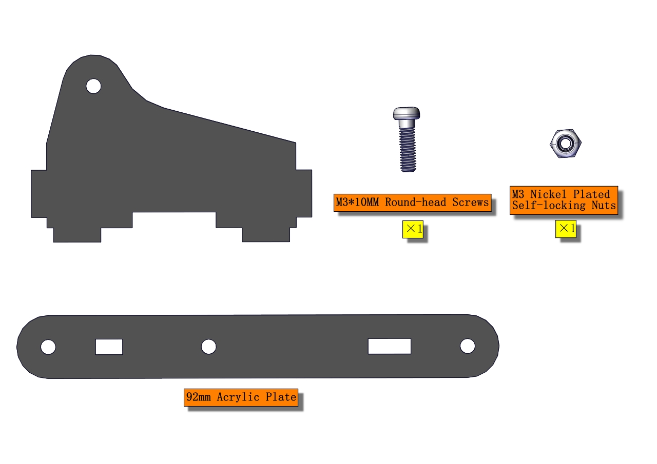
Components Needed:
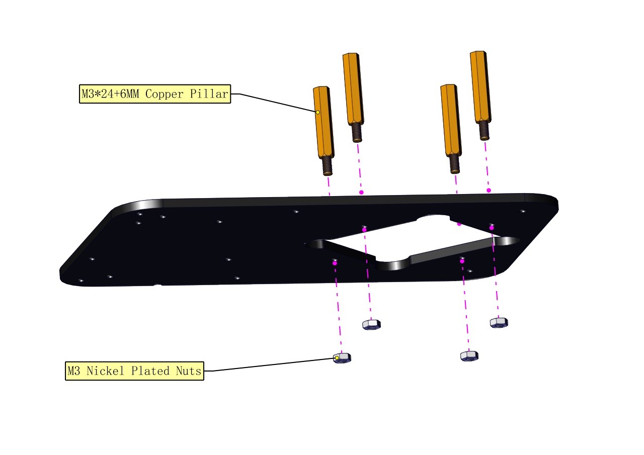
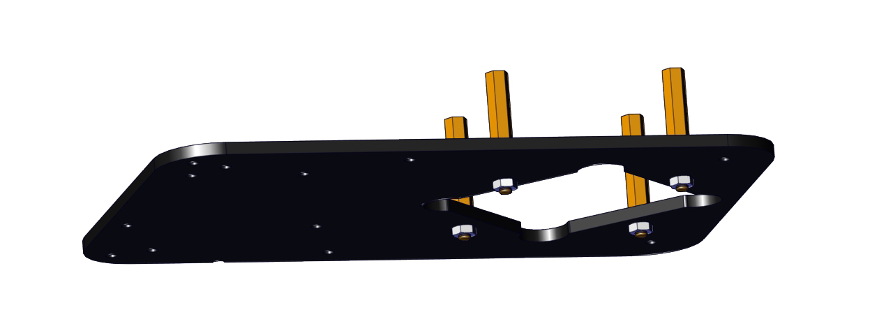
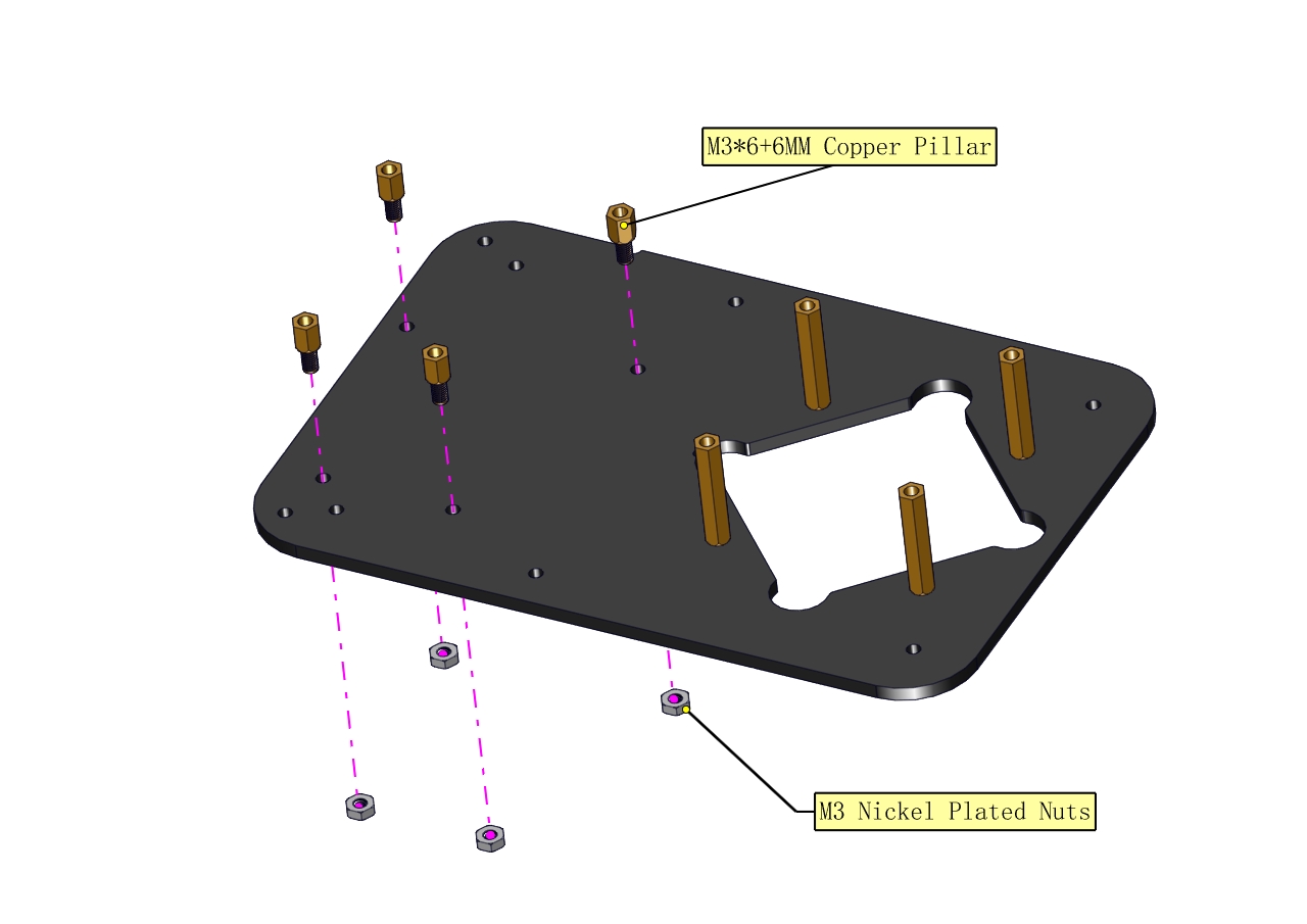
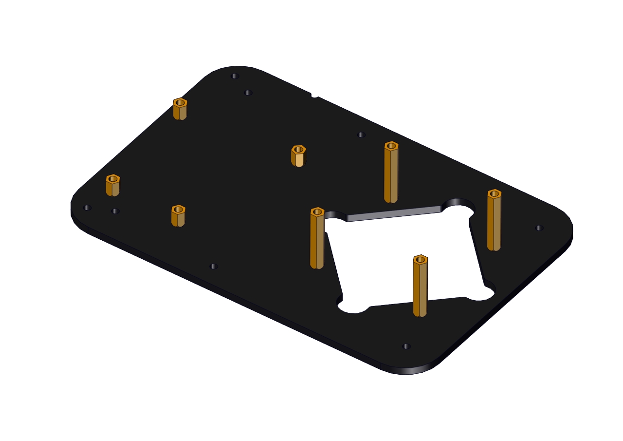
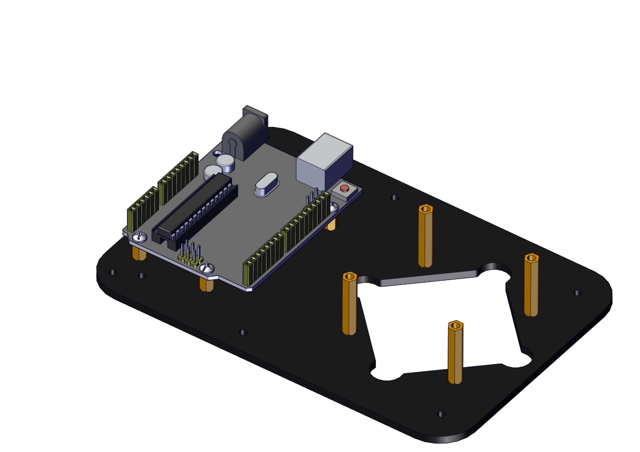
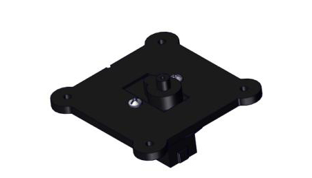
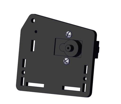
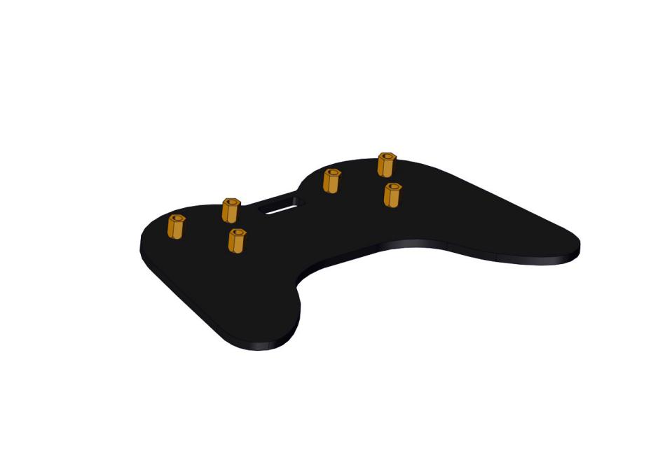
The base is installed successfully.
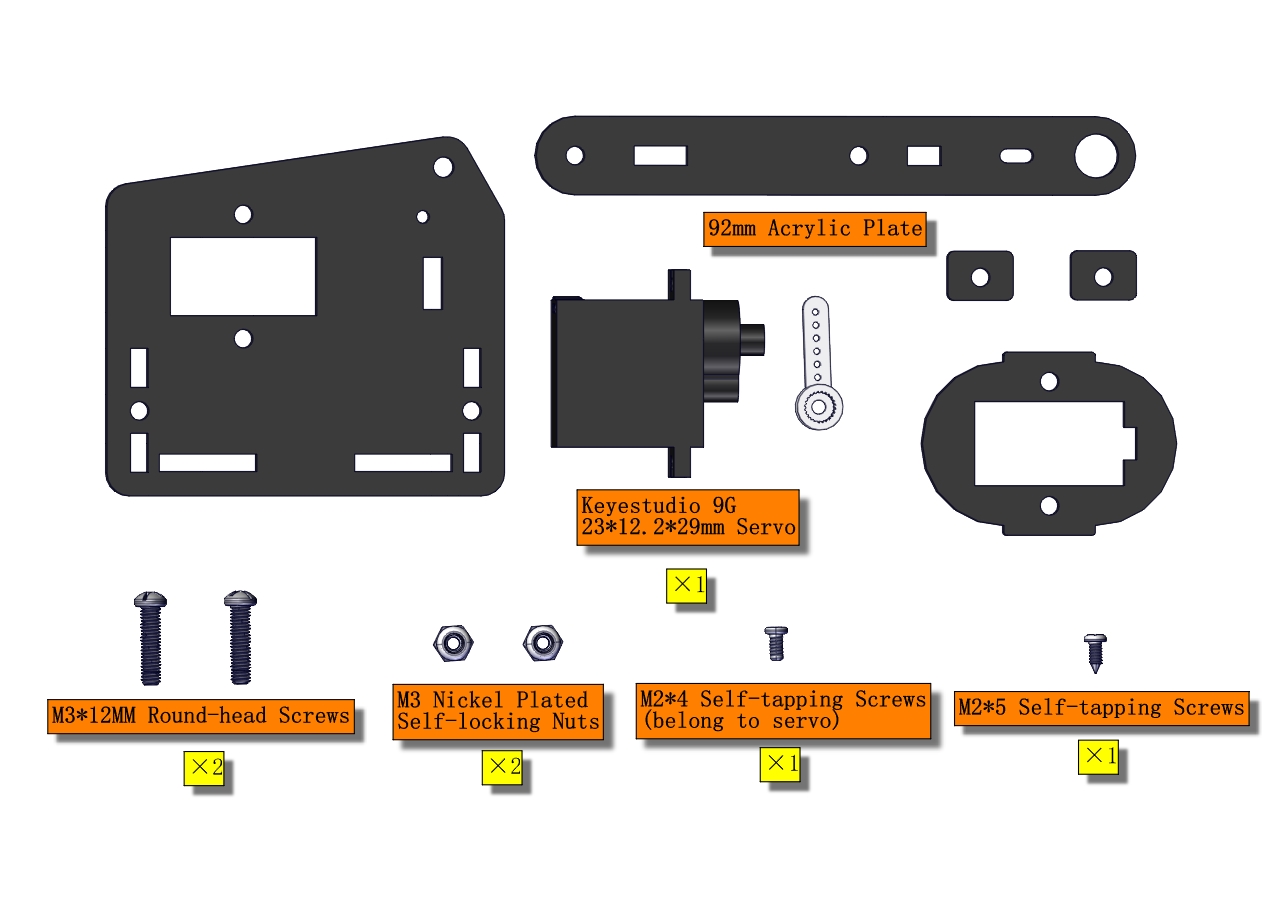
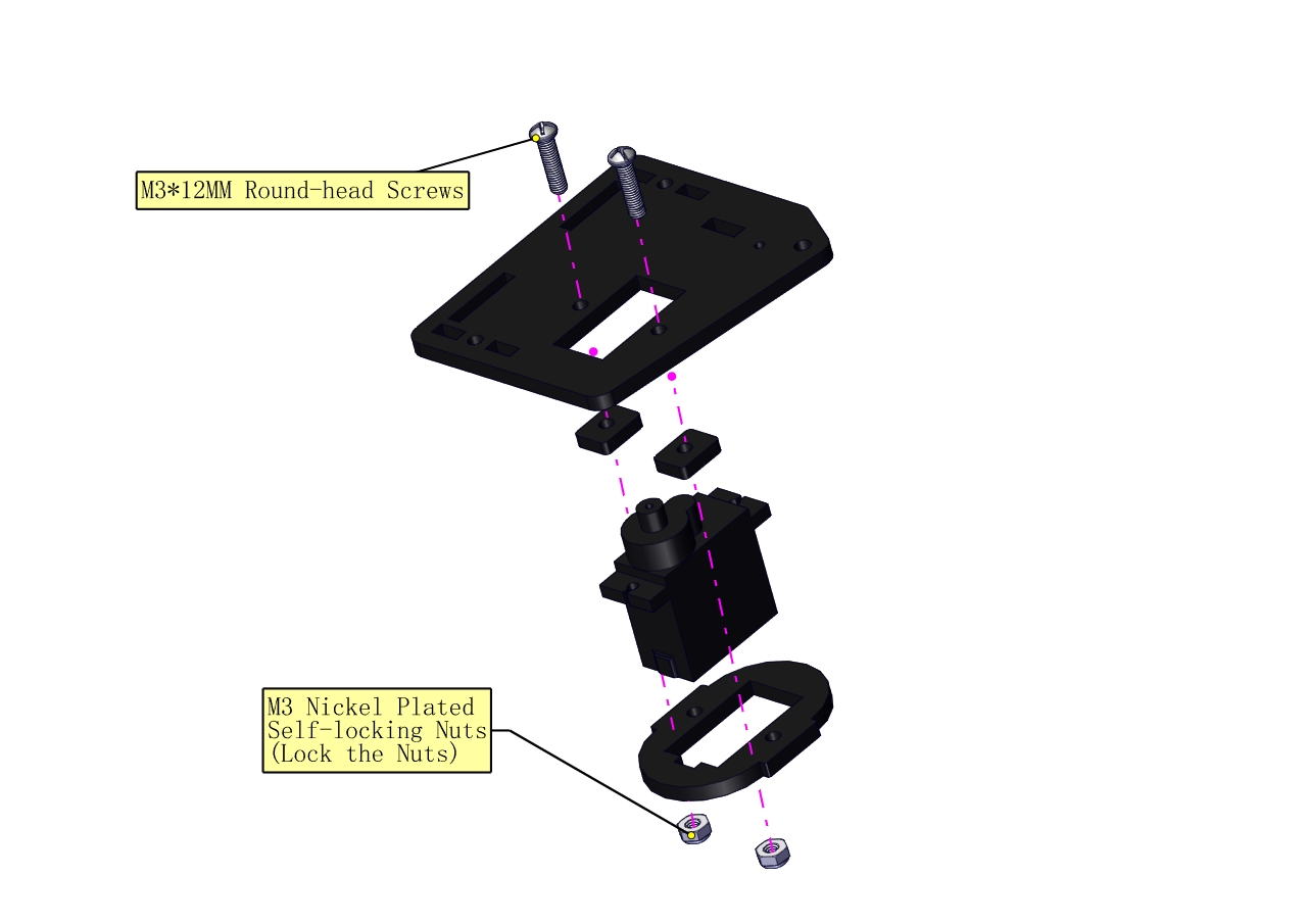
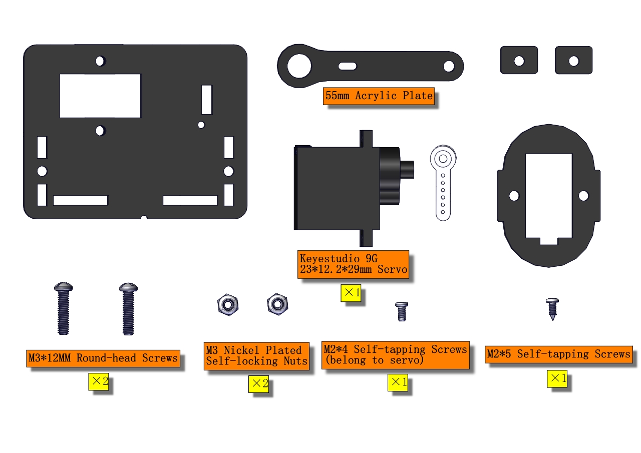
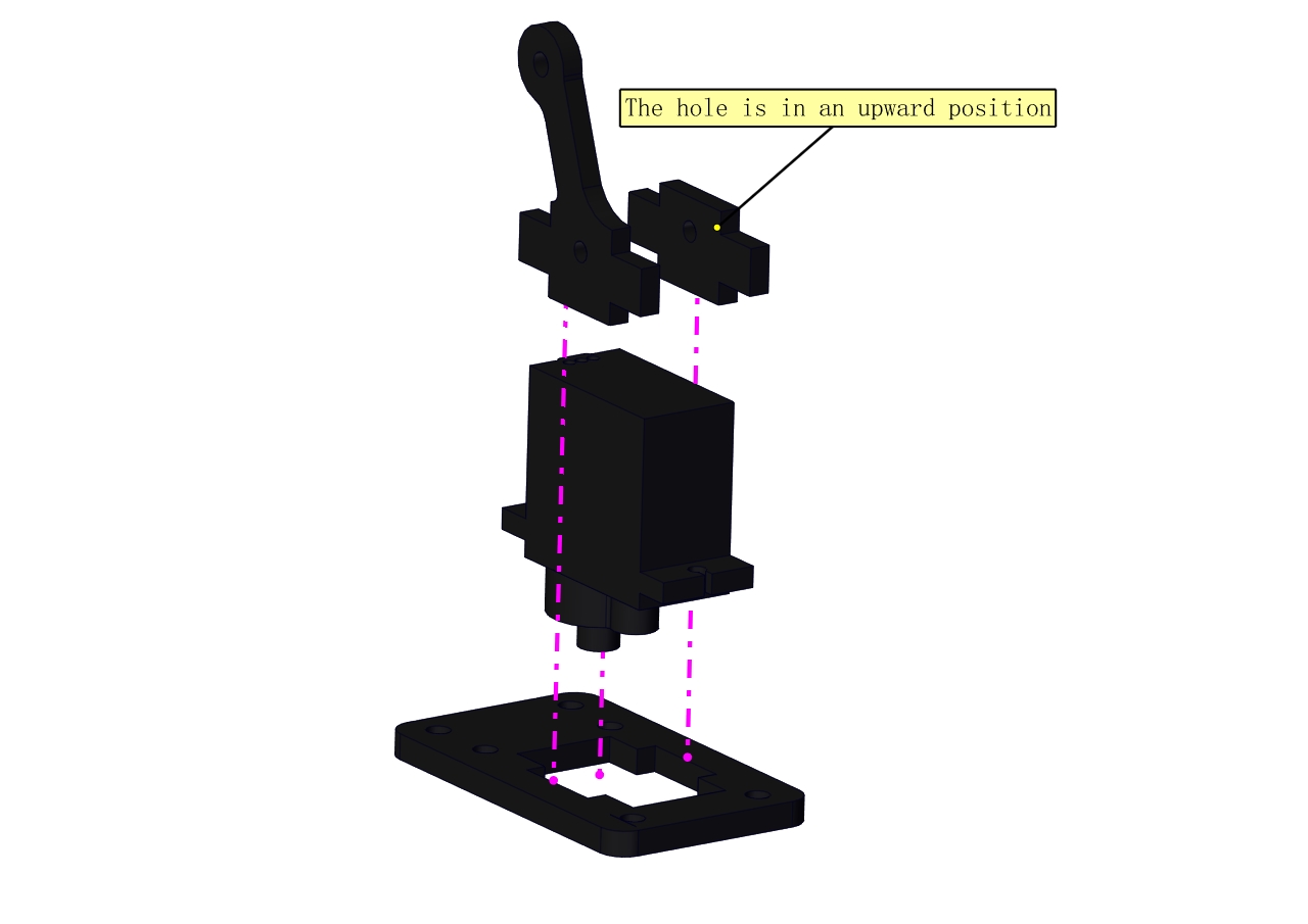
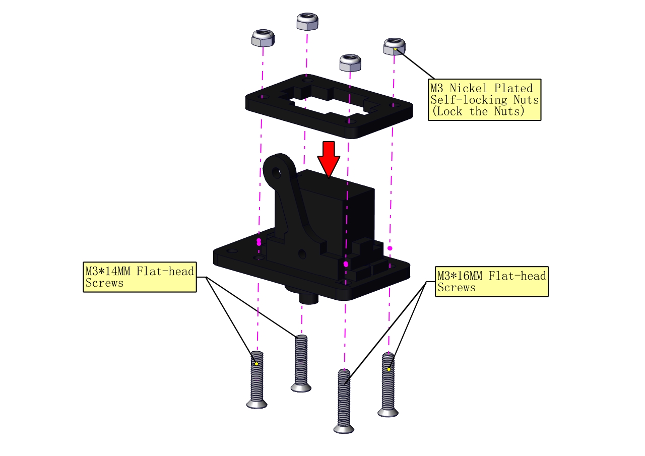
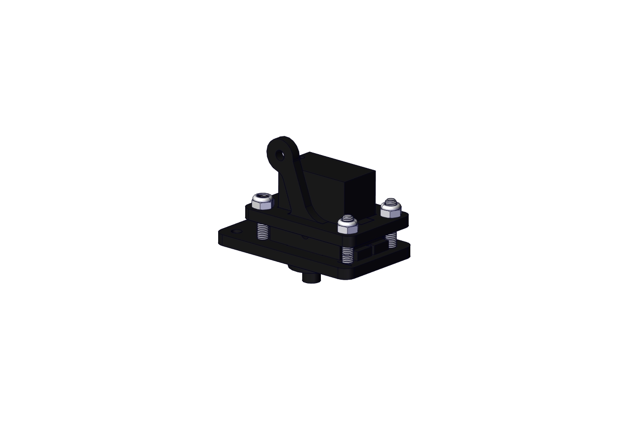
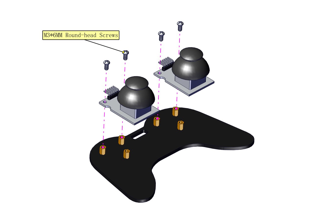
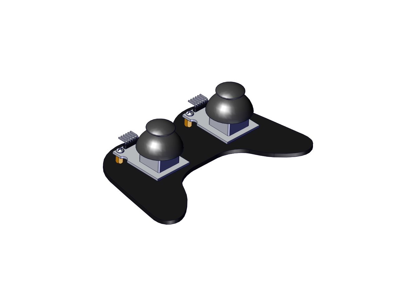
(2) Mount servos onto the base
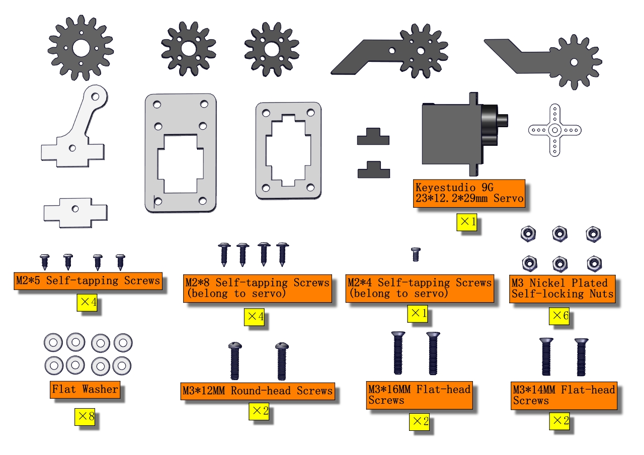
Components Needed:
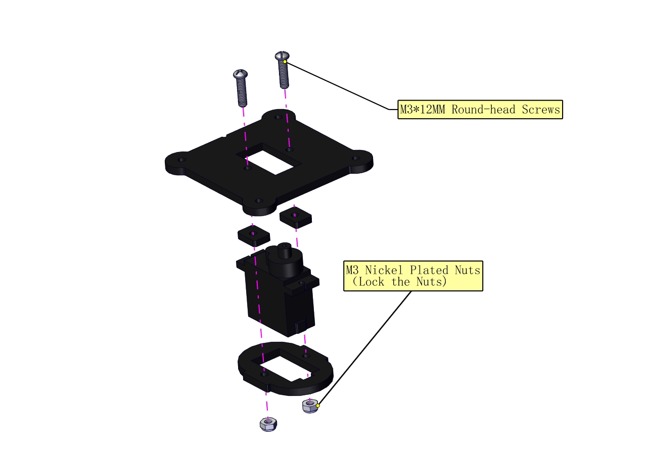
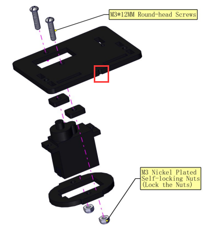
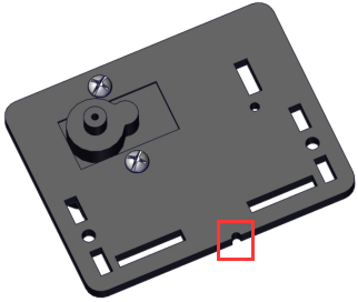
Assemble a servo(left) onto the left board
Components Needed:
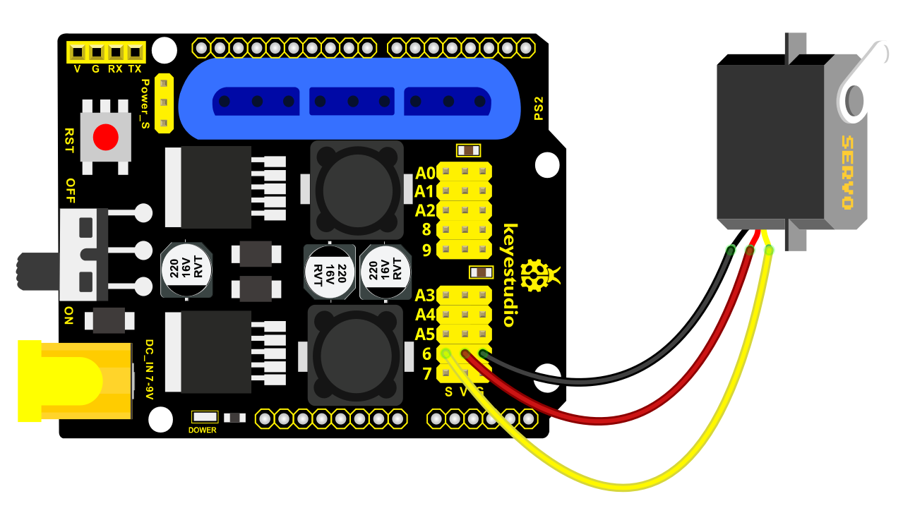
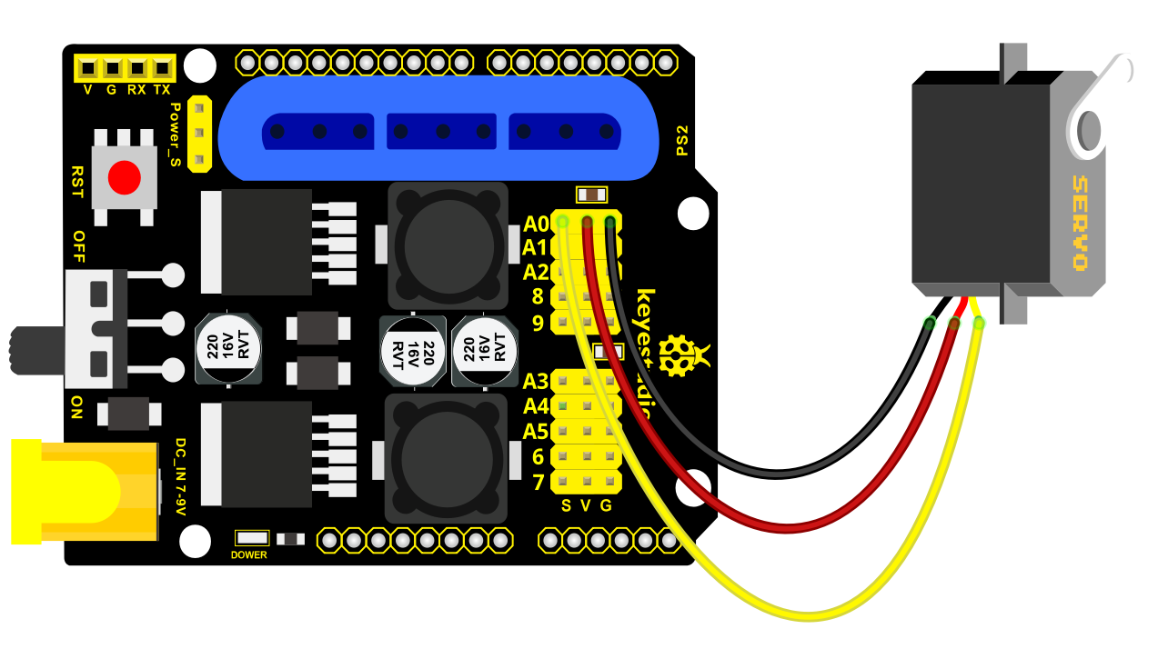
Initialize the left servo
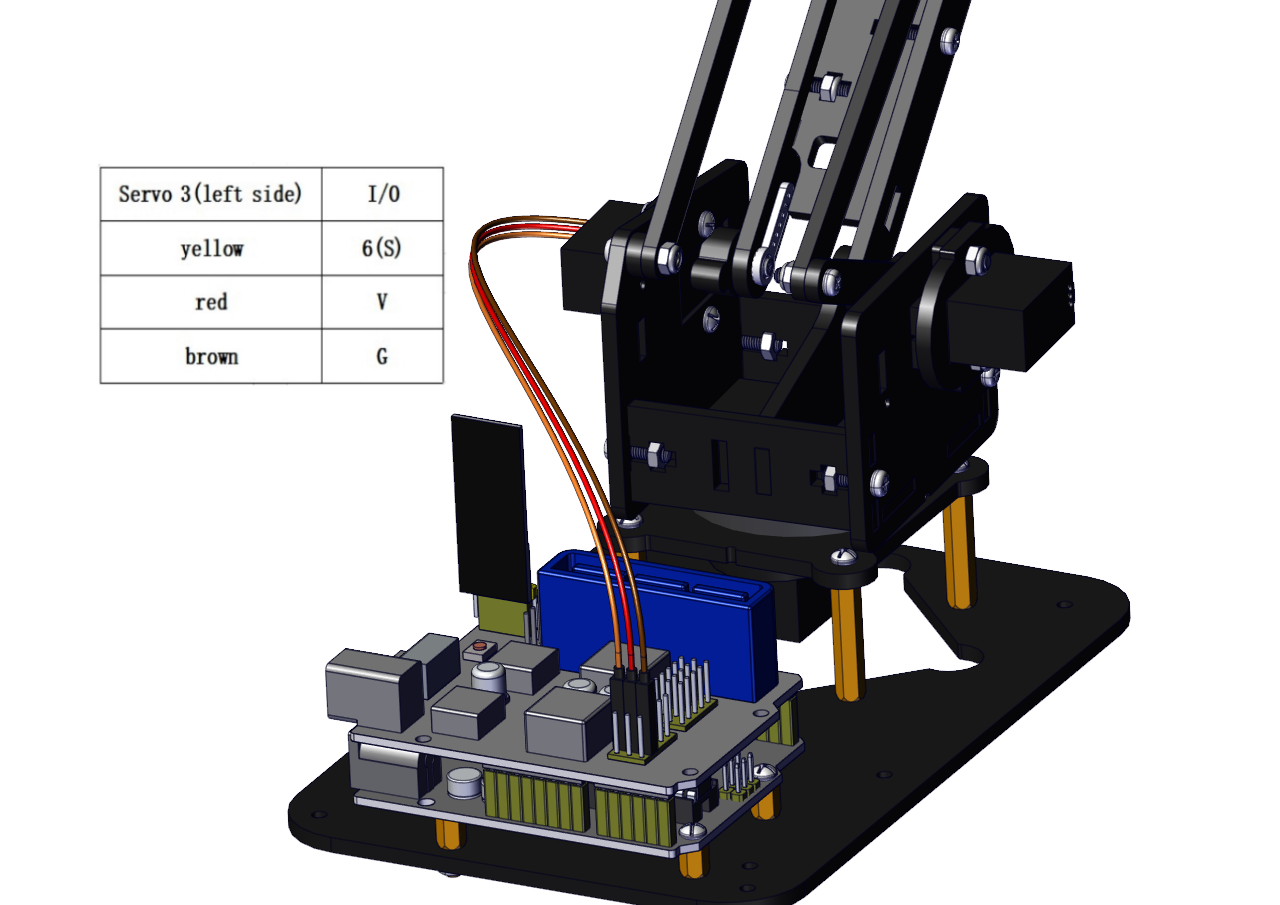
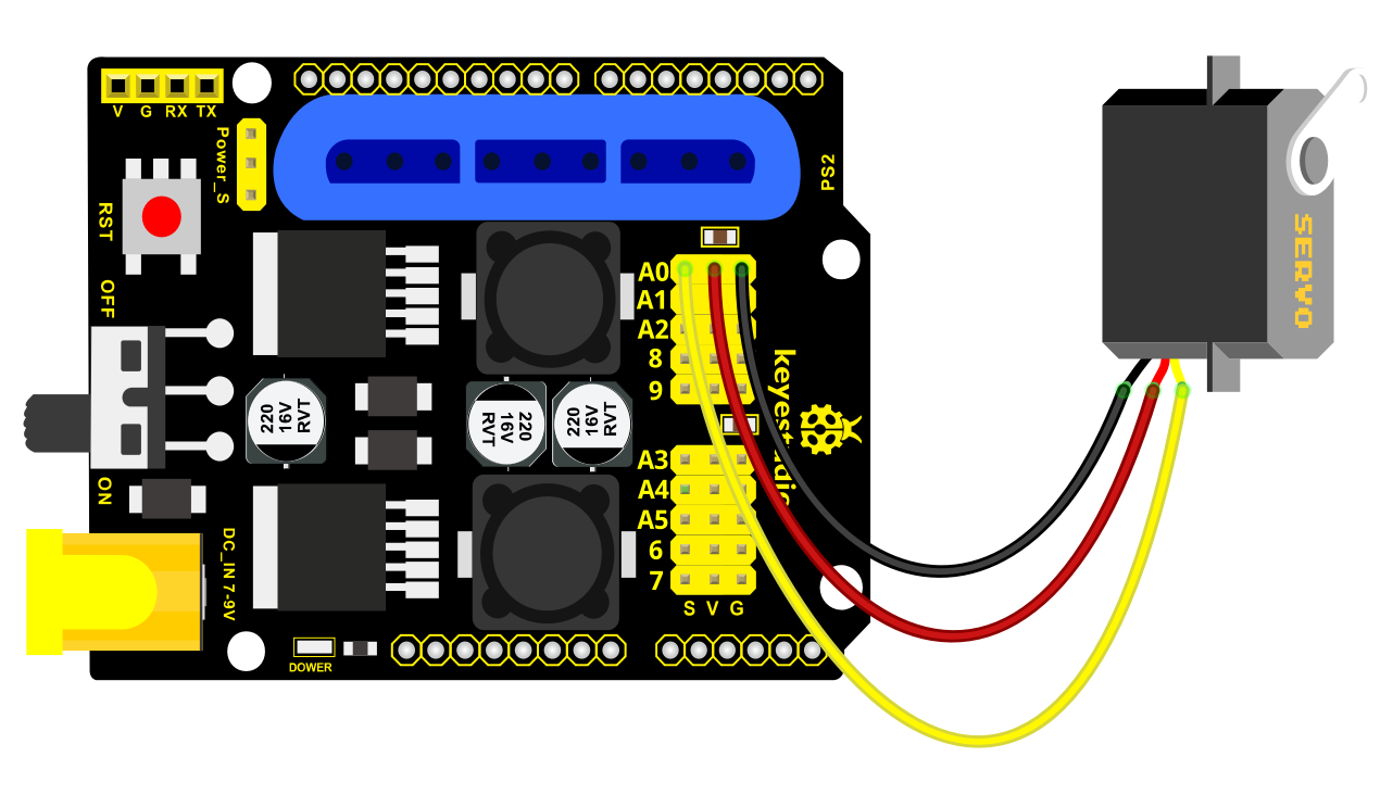
Attach this left servo to G, V and S(6)of servo motor driver shield, upload the following code, plug in power and press the rest button on the V4.0 board. Then the left servo rotates to 180°
Test Code:
#include <Servo.h>

Servo myservo; // create servo object to control a servo

void setup()

{

Serial.begin(9600);

delay(1000);

}

void loop()

{

myservo.attach(6); // Change pin to adjust one by one

myservo.write(180); //Angle

delay(1000);

}

a. Fix the arm:

Mount a servo(right) onto the right board
Components Needed
Note the breach direction of acrylic board
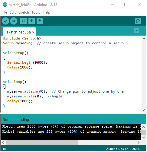
b. Initialize the right servo
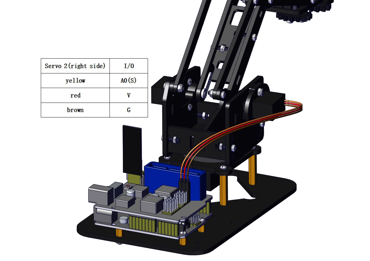
Attach this left servo to G, V and S(A0)of servo motor driver shield, upload the following code, plug in power and press the rest button on the V4.0 board. Then the left servo rotates to 0°
Set the servo to 0°:
#include <Servo.h>

Servo myservo; // create servo object to control a servo

void setup()

{

Serial.begin(9600);

delay(1000);

}

void loop()

{

myservo.attach(A0); // Change pin to adjust one by one

myservo.write(0); //Angle

delay(1000);

}
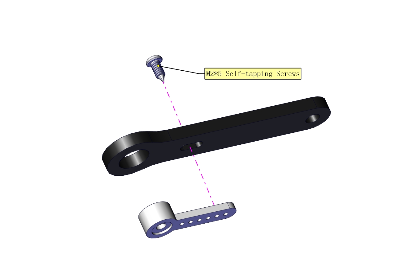
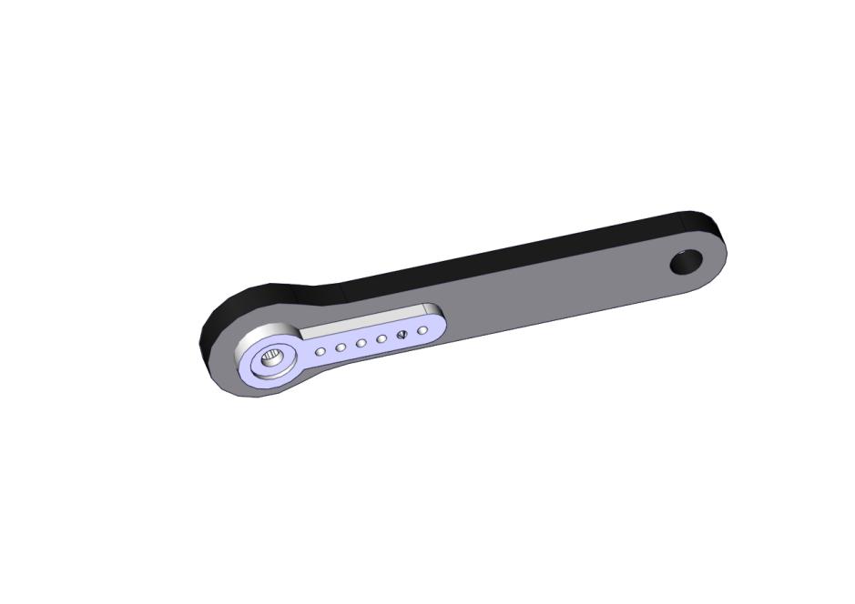
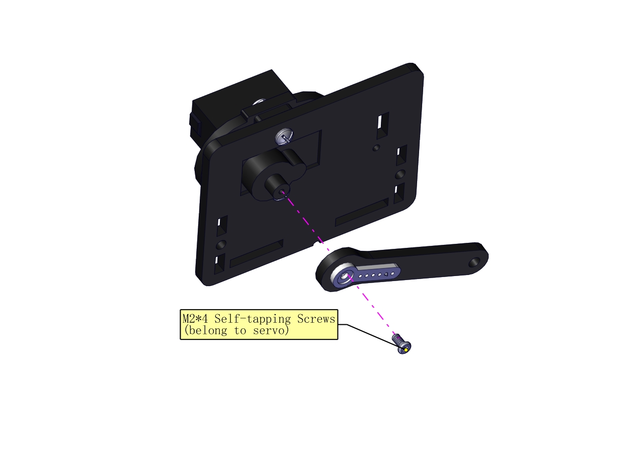
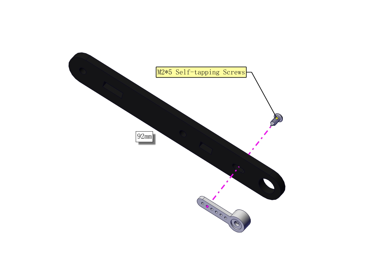
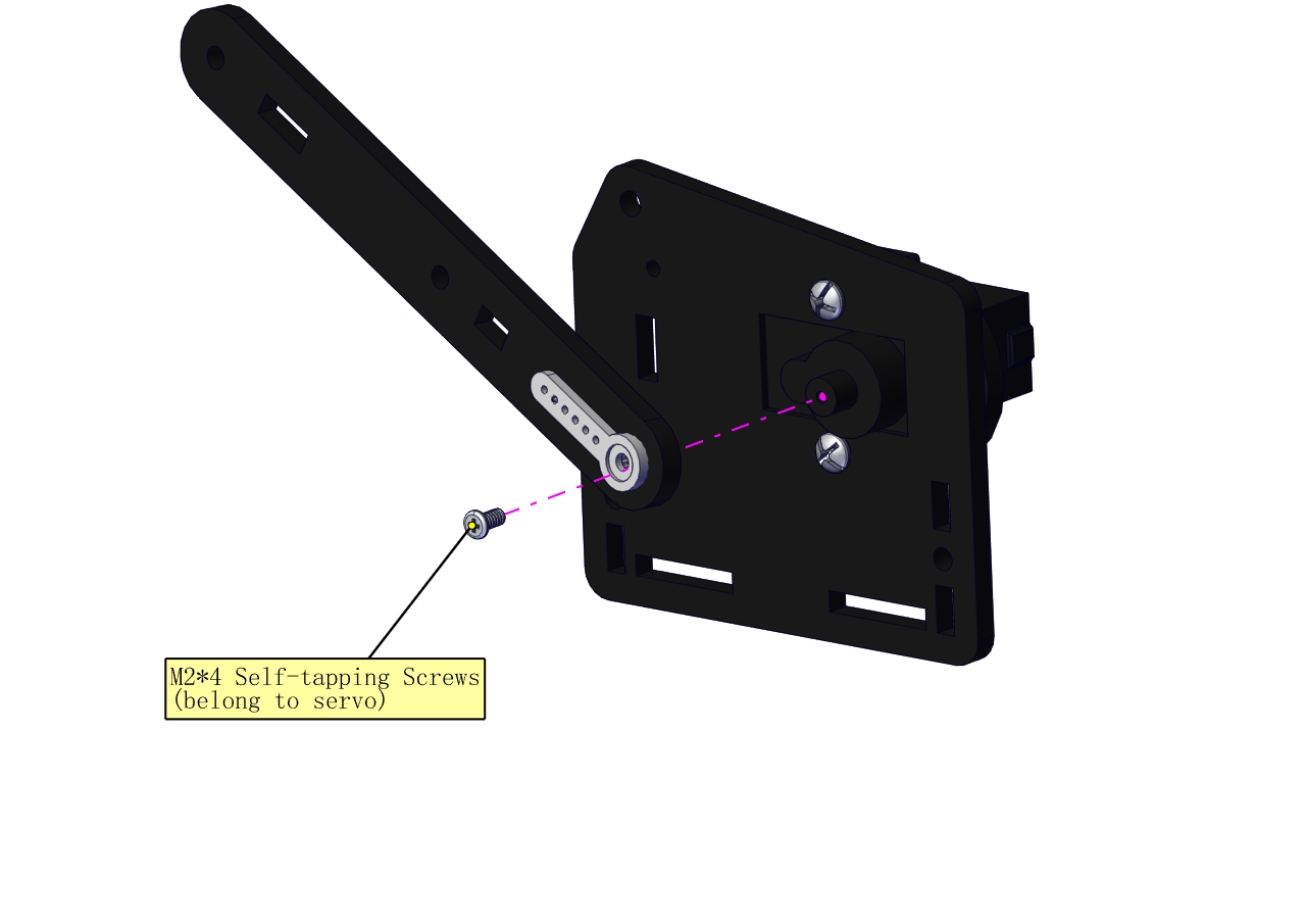
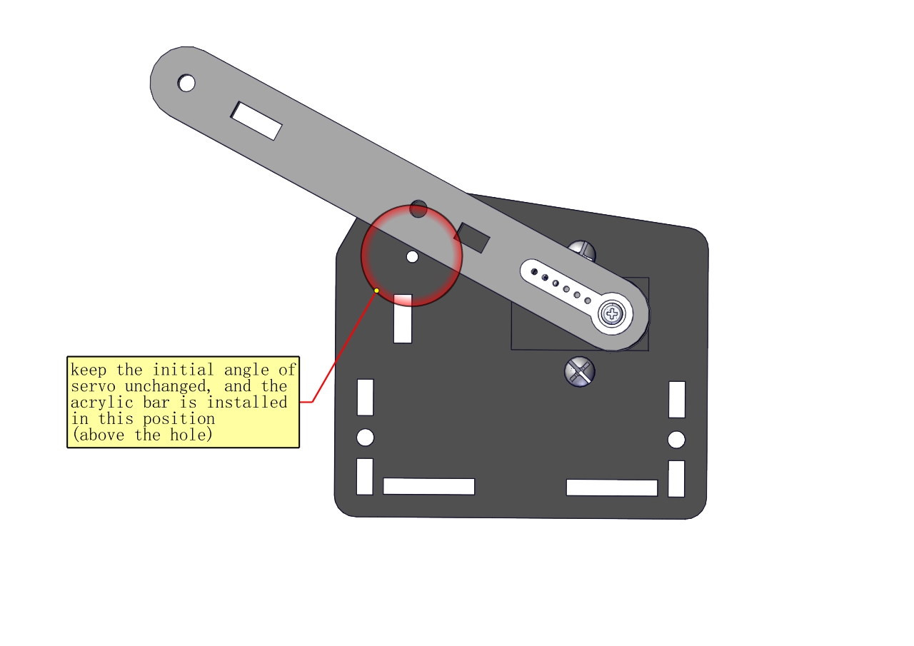
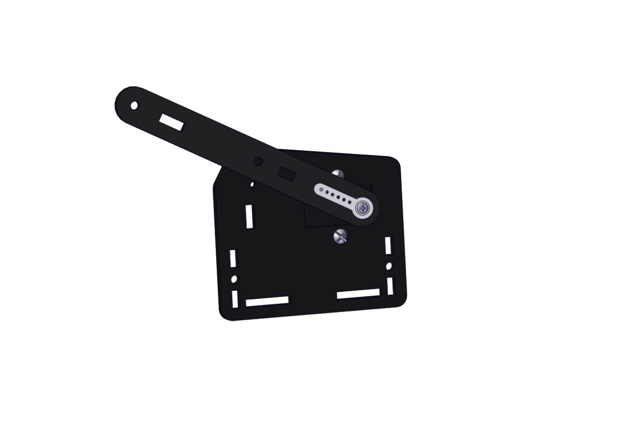
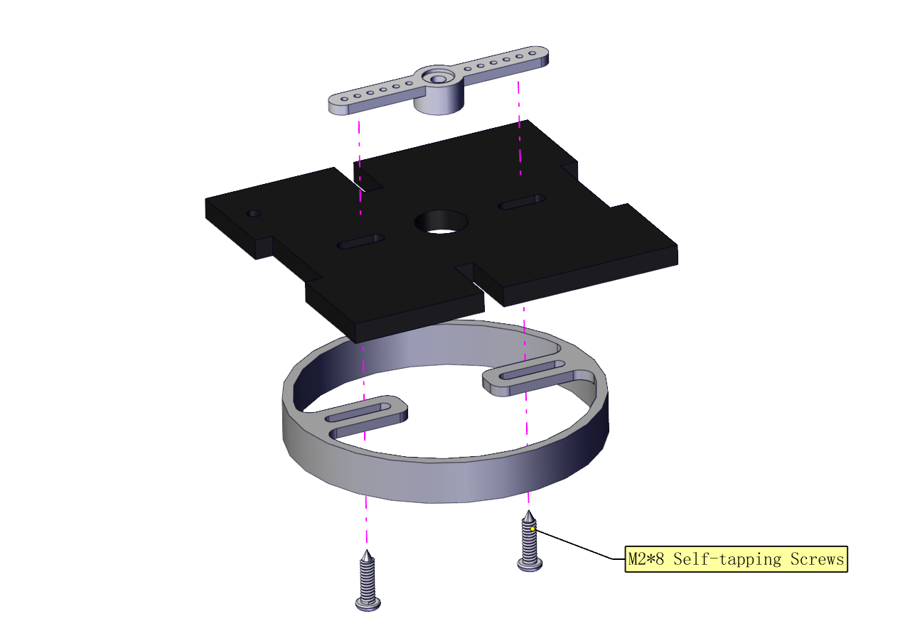
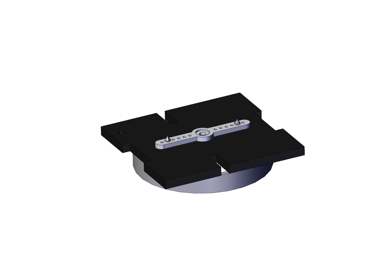
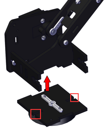
Install the holder part
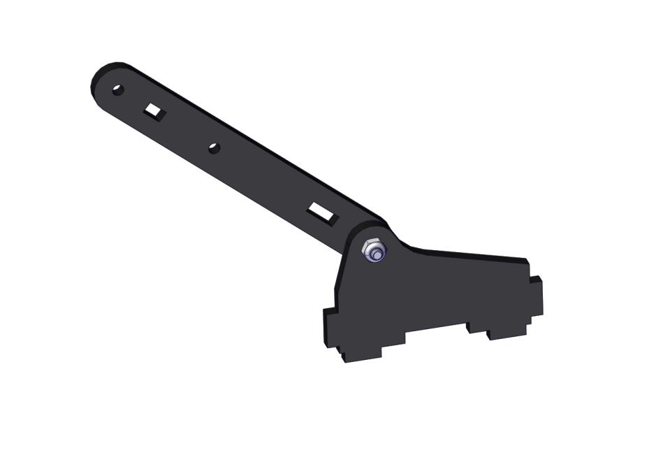
Fix the left part and the mount part together
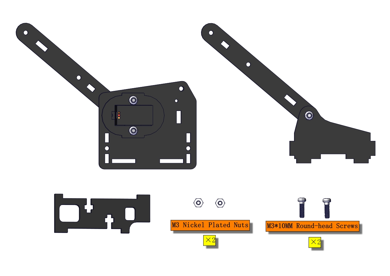
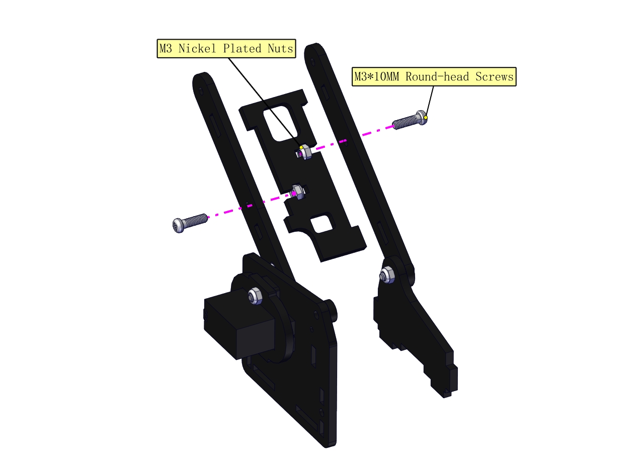
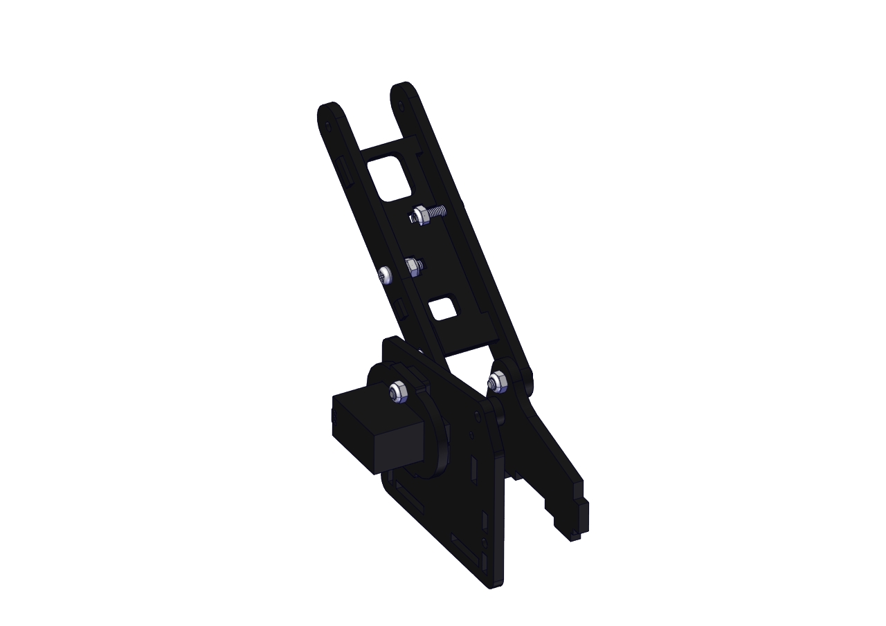
Fix the right part and the ABS holder together.
Note the direction of the ABS holder.
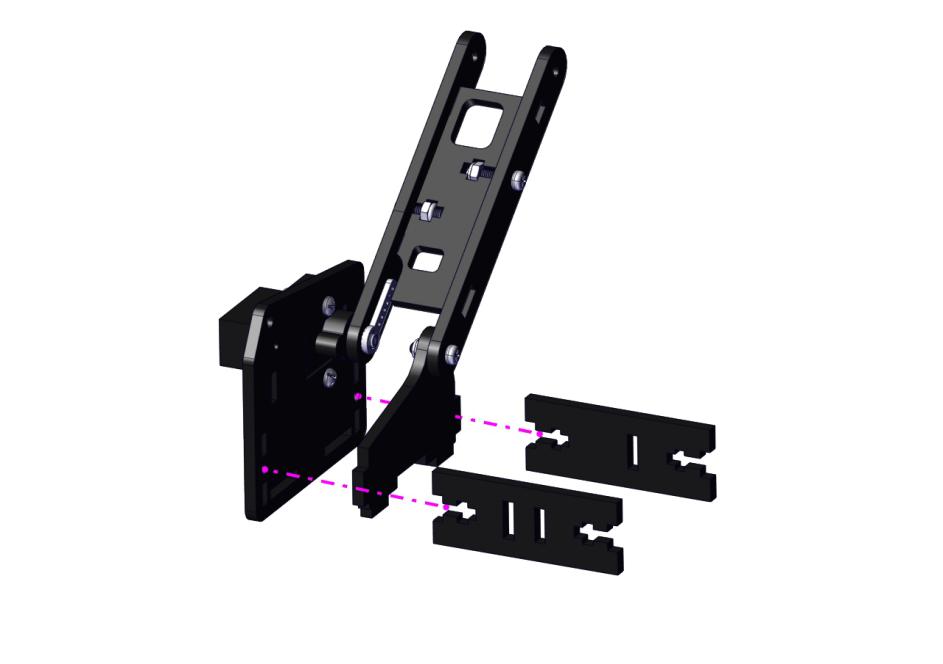
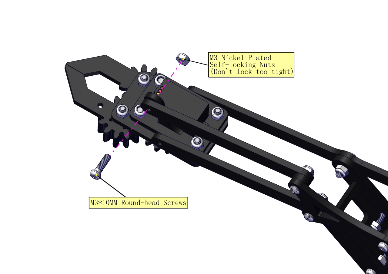
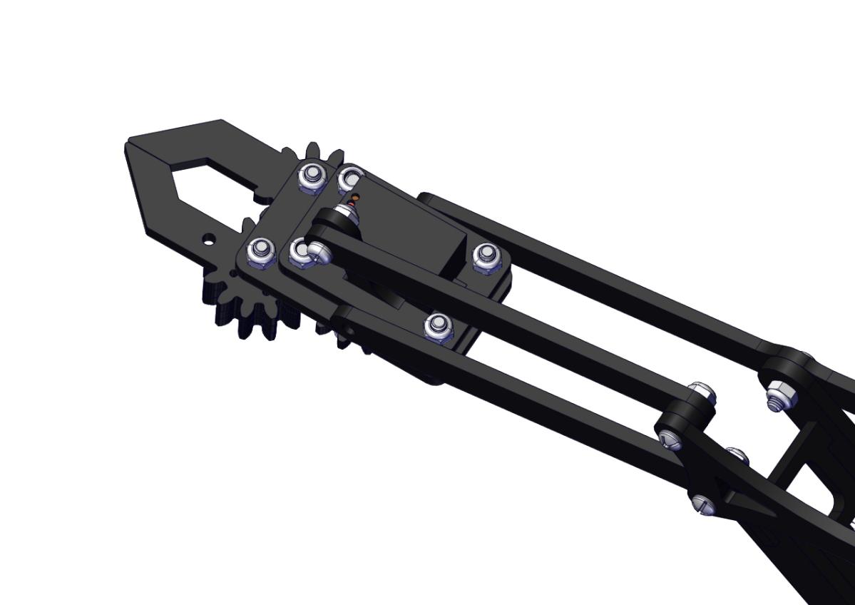
Install the middle part


Assemble the claw
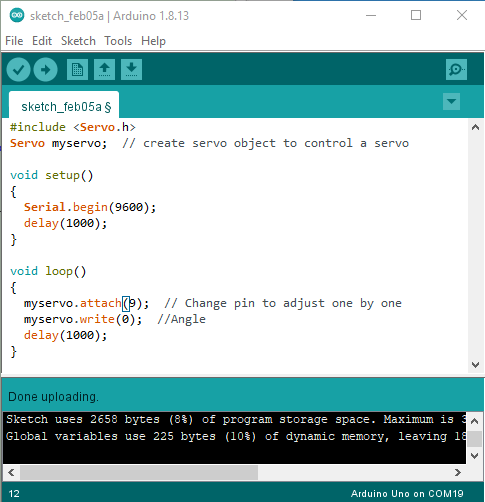
c. Initialize the servo
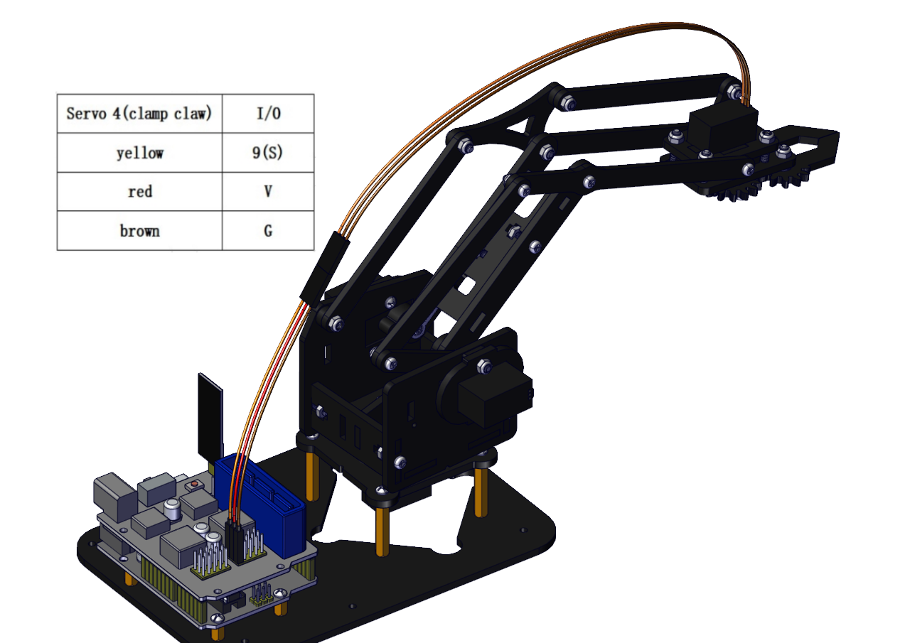
Attach this left servo to G, V and S(9)of servo motor driver shield, upload the following code, plug in power and press the rest button on the V4.0 board. Then the left servo rotates to 0°
Set the servo to 0°:
#include <Servo.h>

Servo myservo; // create servo object to control a servo

void setup()

{

Serial.begin(9600);

delay(1000);

}

void loop()

{

myservo.attach(9); // Change pin to adjust one by one

myservo.write(0); //Angle

delay(1000);

}
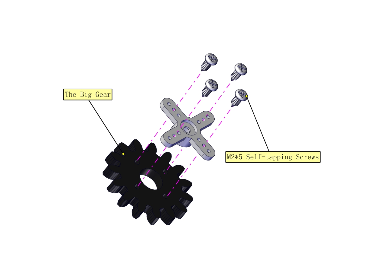
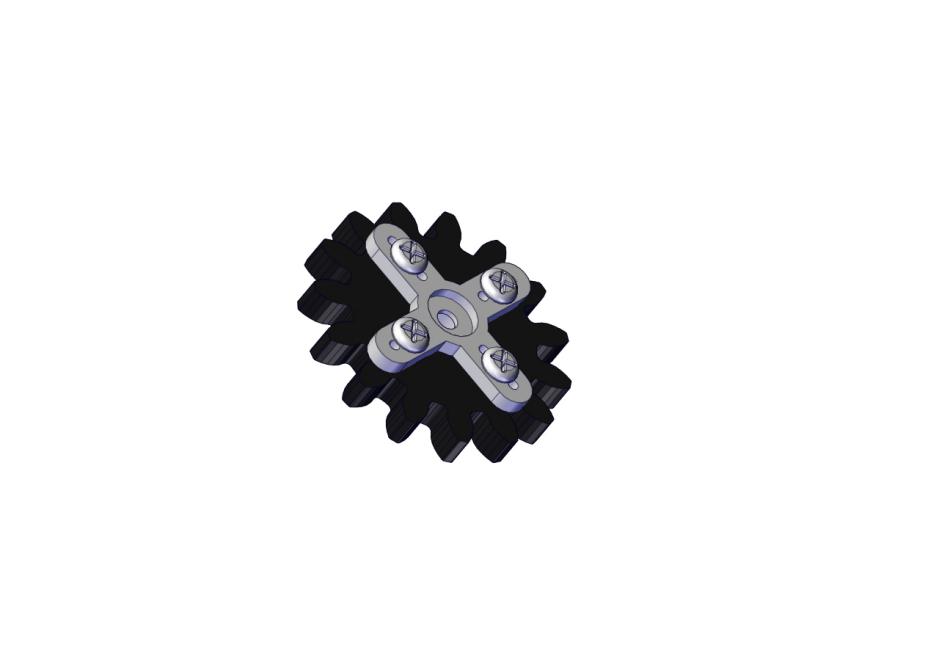
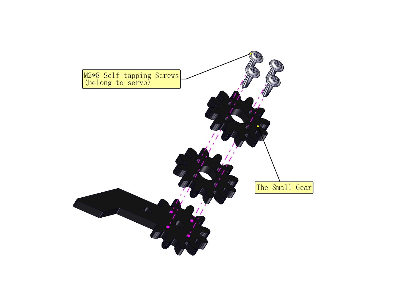
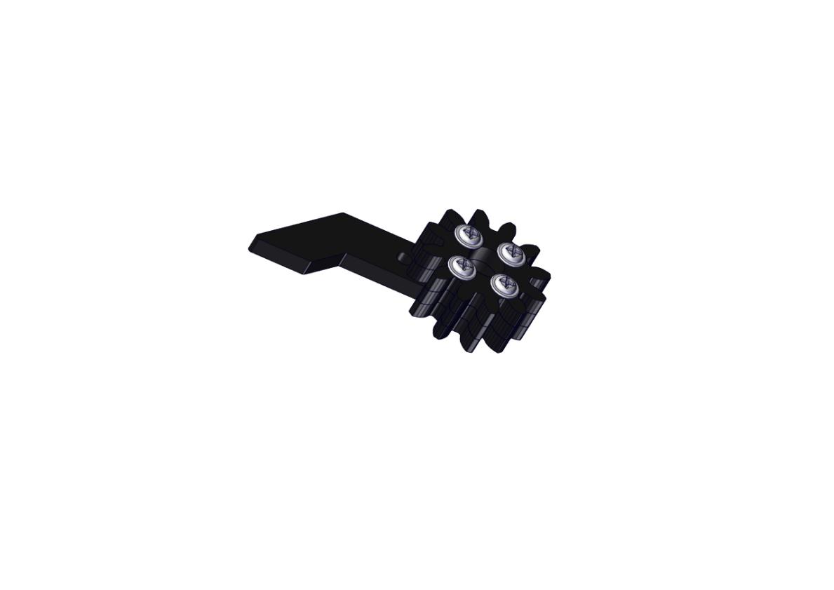
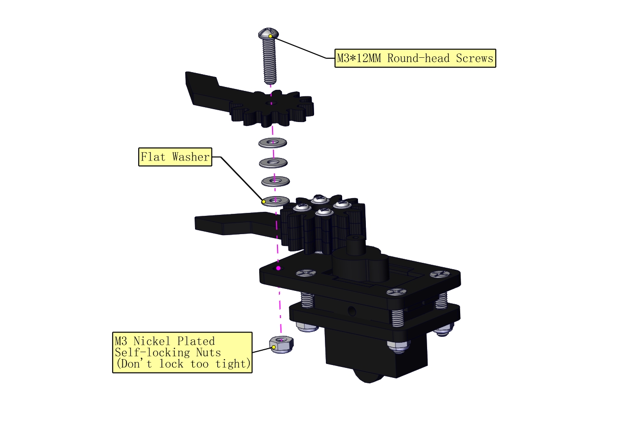
Mount gear wheels:
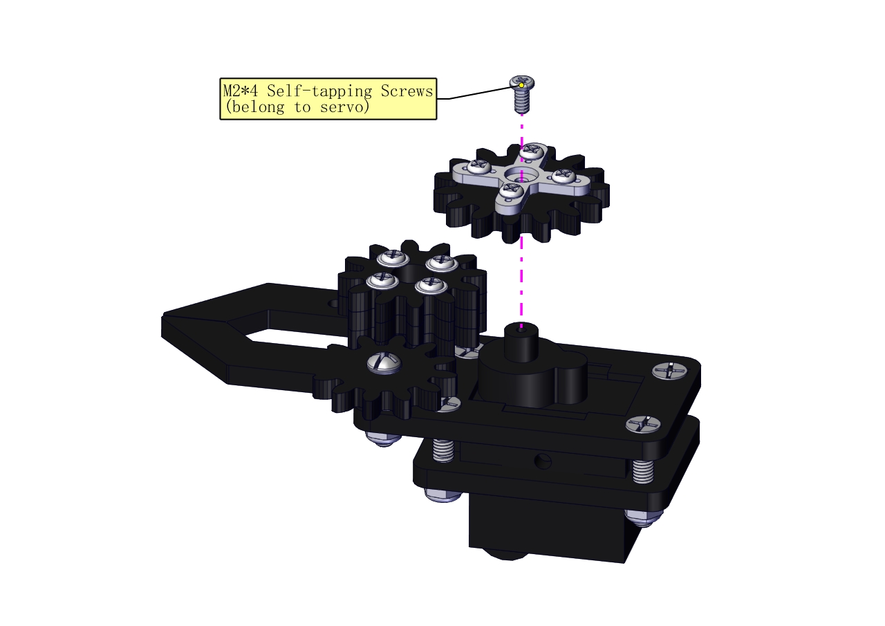
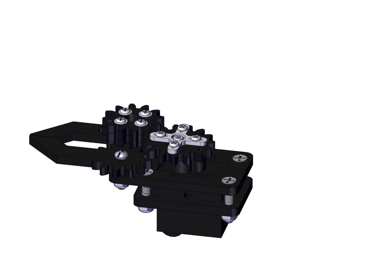
Components Needed:
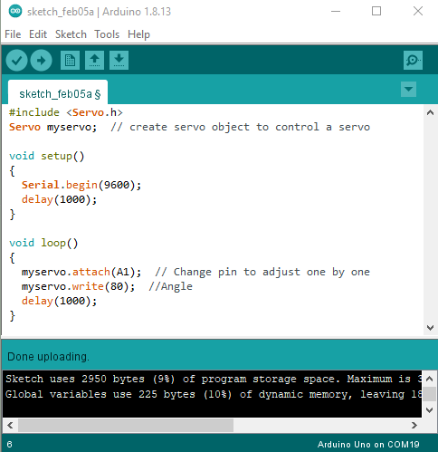
Initialize the servo
Attach this left servo to G, V and S(A1)of sevro motor driver shield, upload the following code, plug in power and press the rest button on the V4.0 board. Then the left servo rotates to 80°
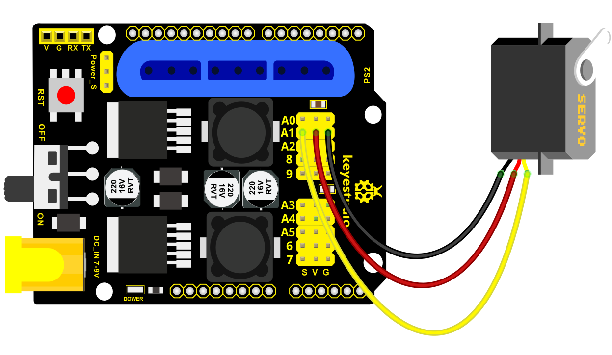
Set the servo to 80°:
#include <Servo.h>

Servo myservo; // create servo object to control a servo

void setup()

{

Serial.begin(9600);

delay(1000);

}

void loop()

{

myservo.attach(A1); // Change pin to adjust one by one

myservo.write(80); //Angle

delay(1000);

}
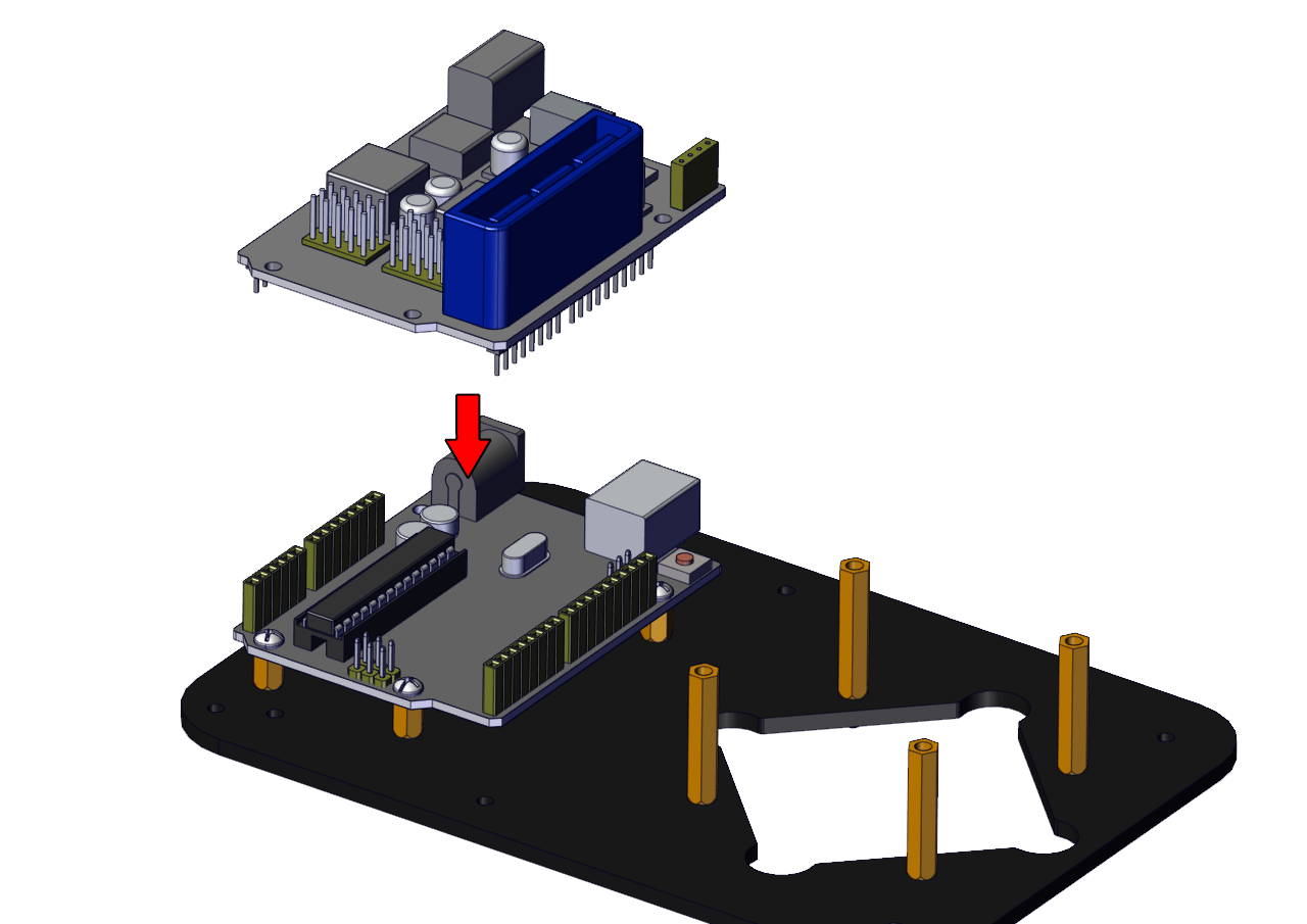
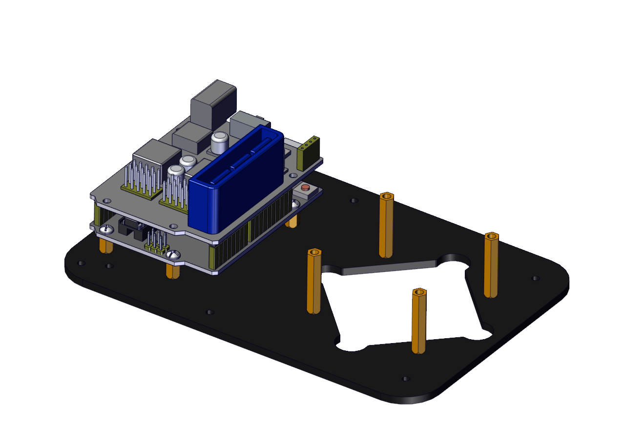
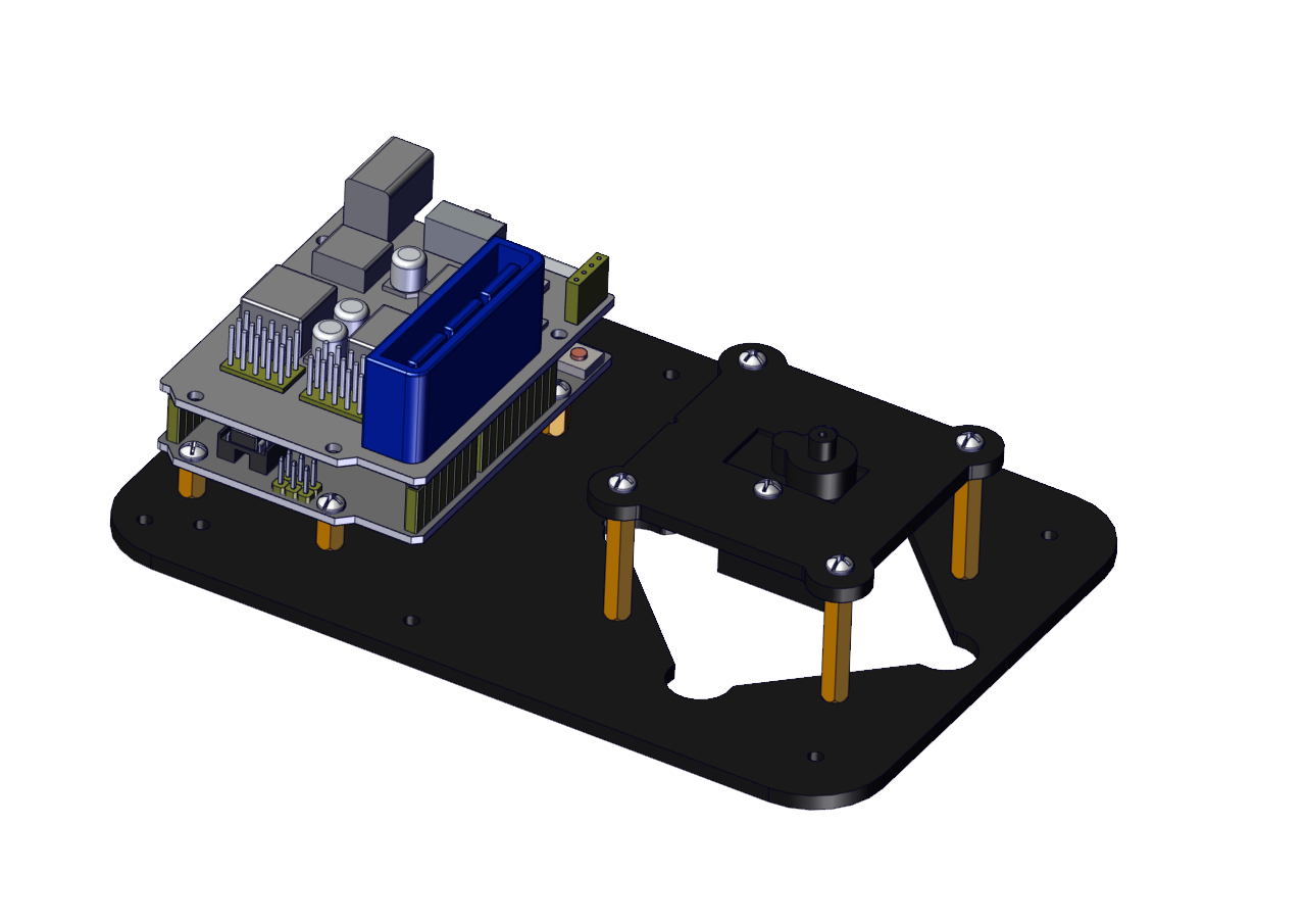
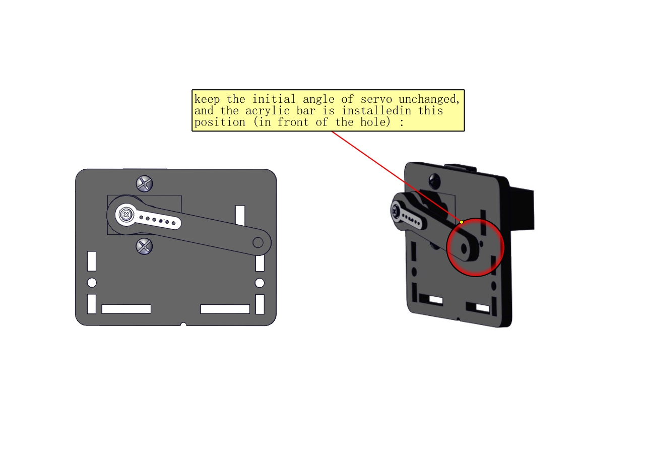
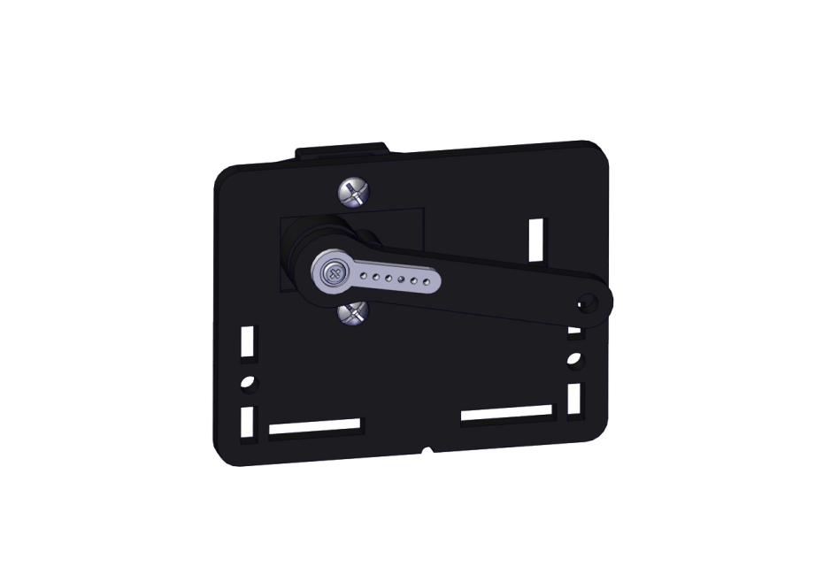
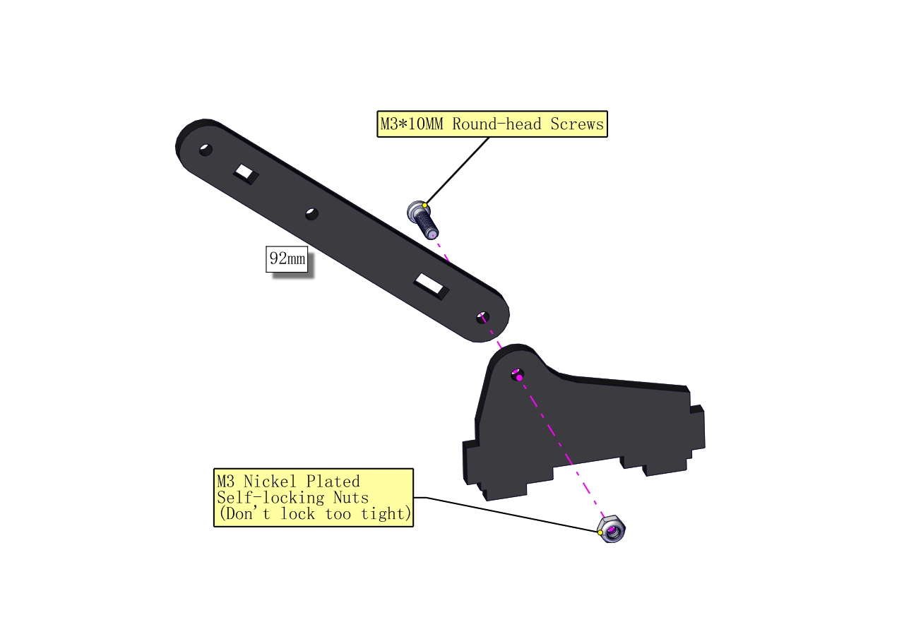
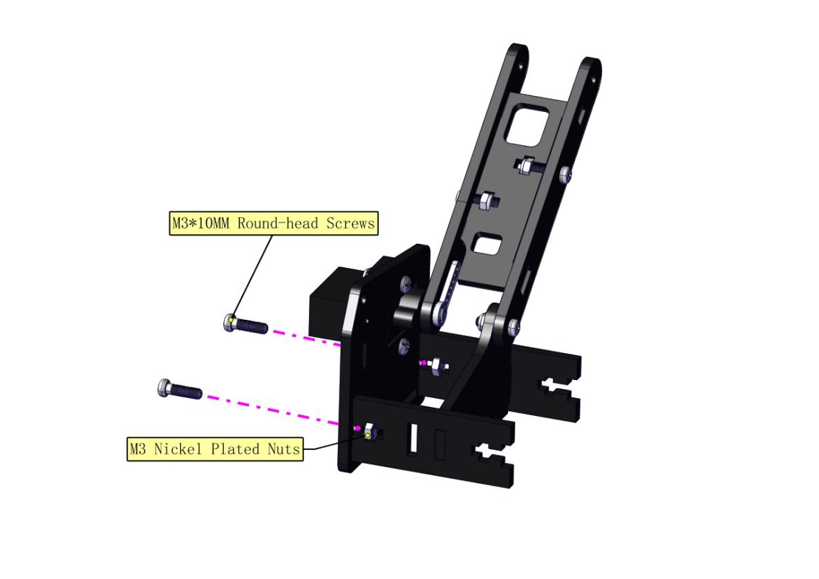
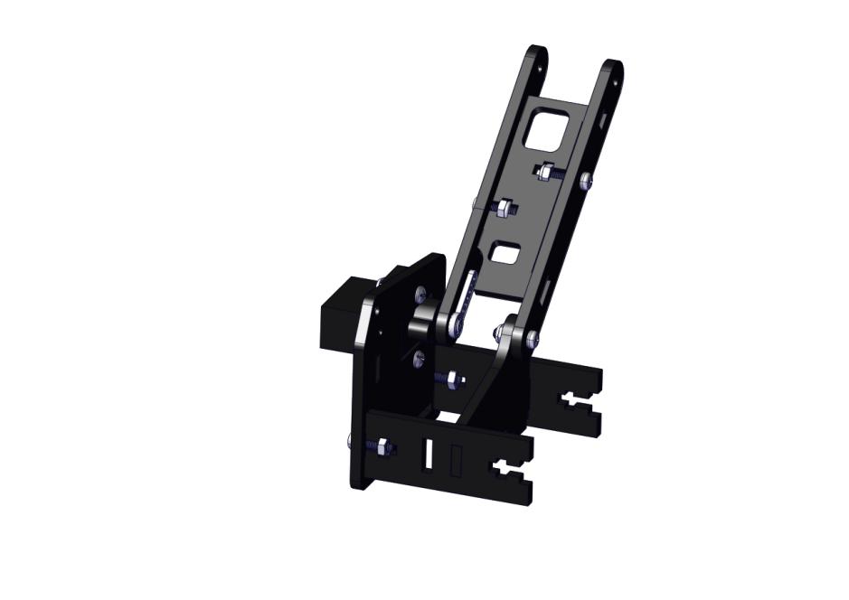
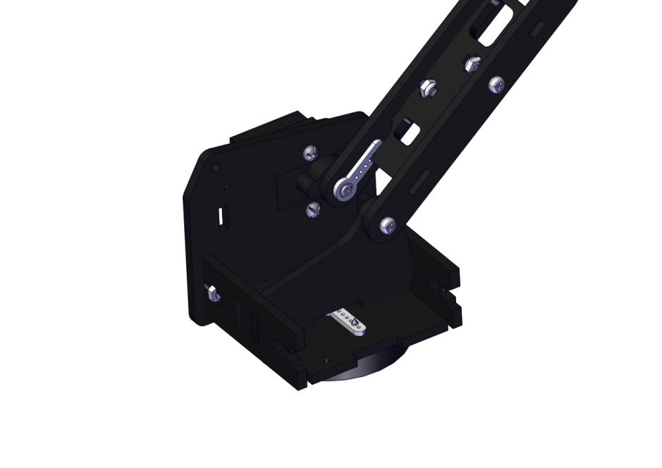
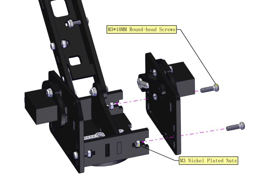
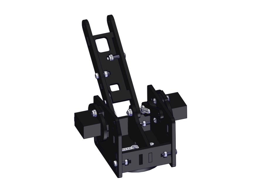
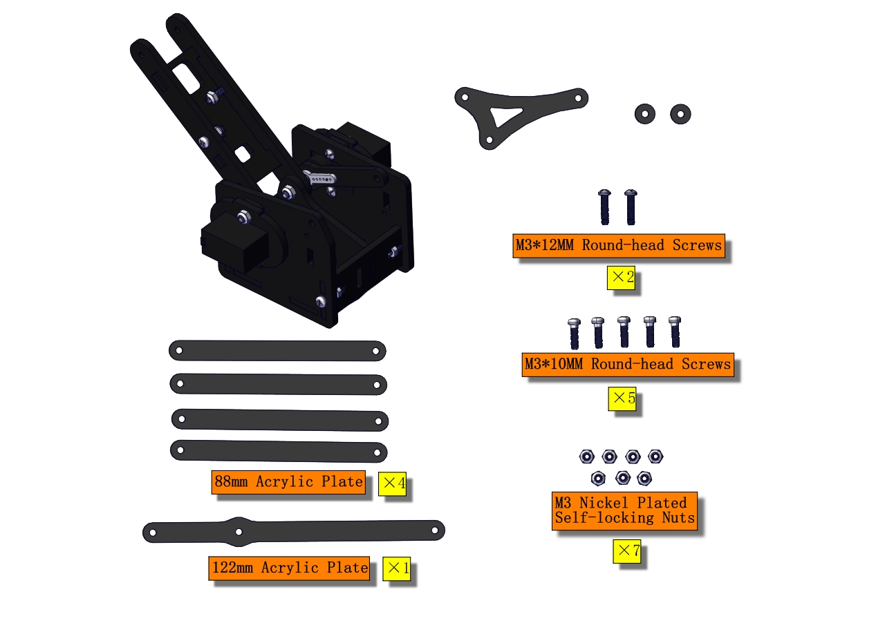
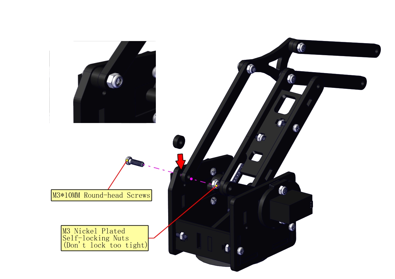
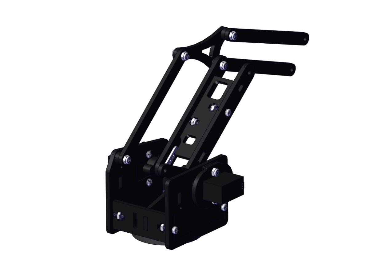
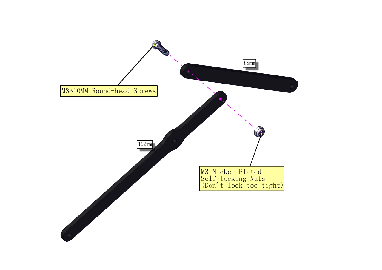
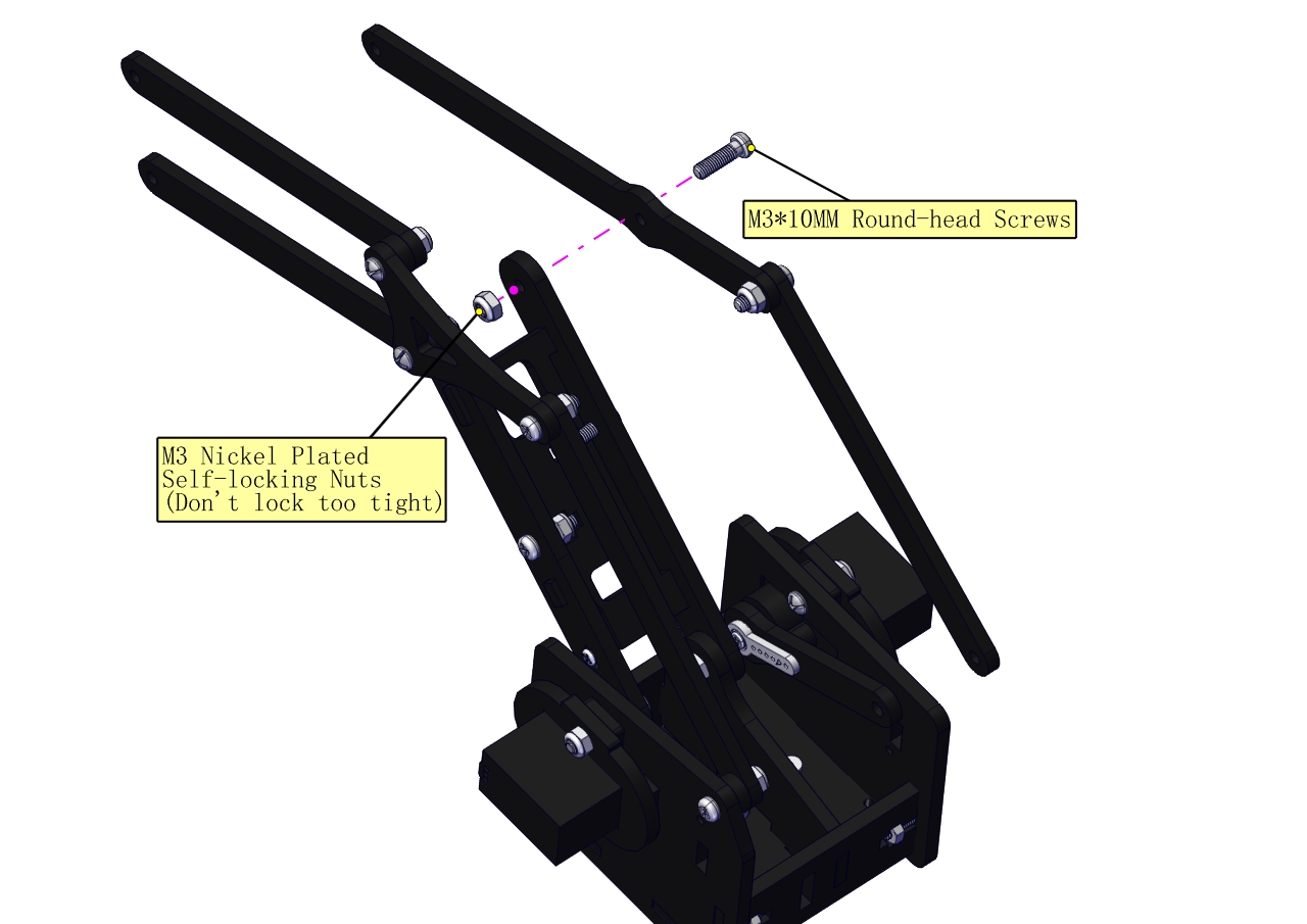
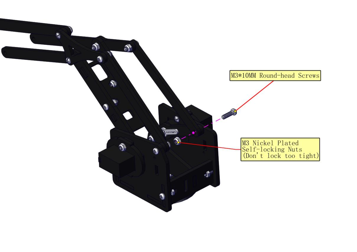
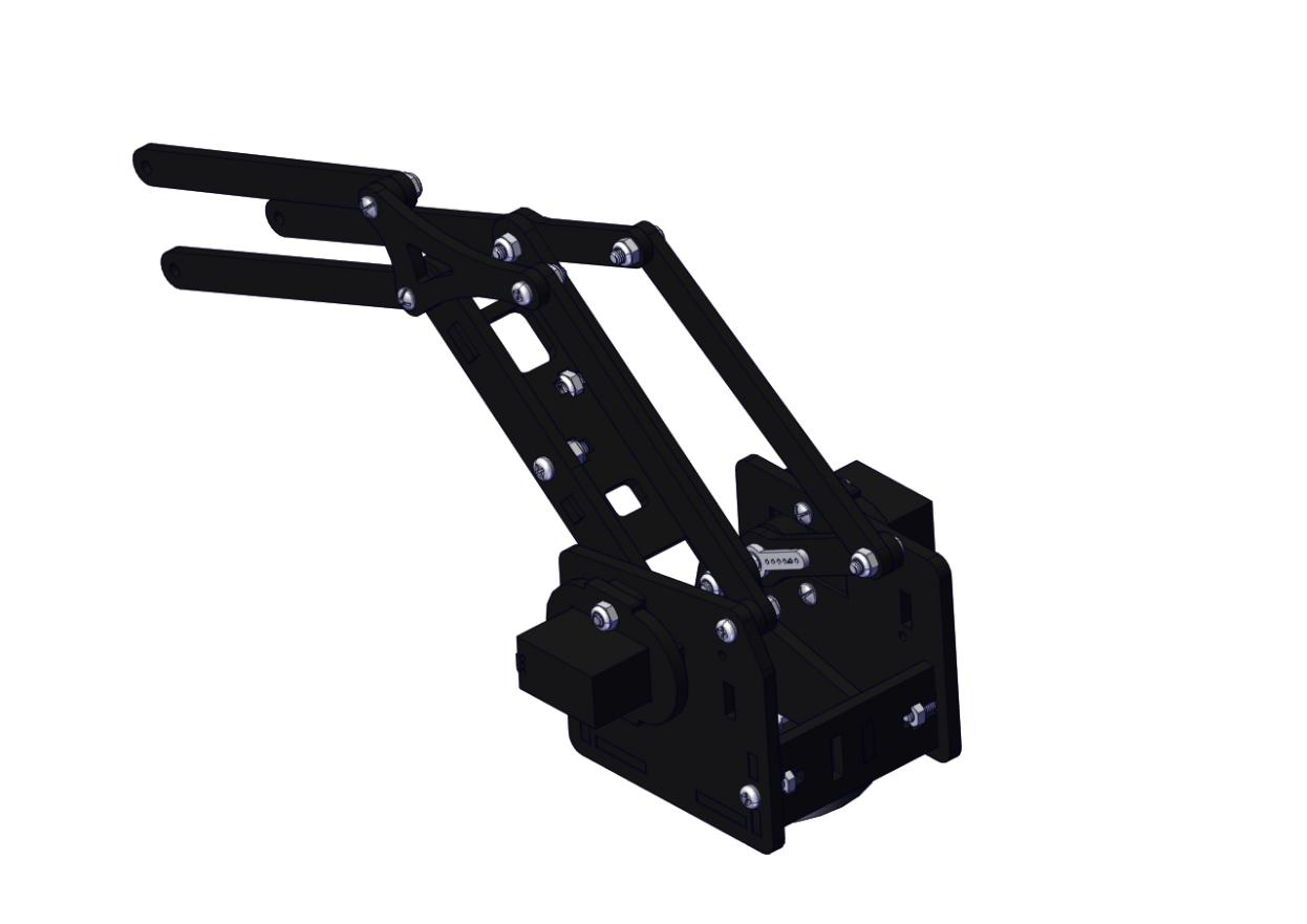
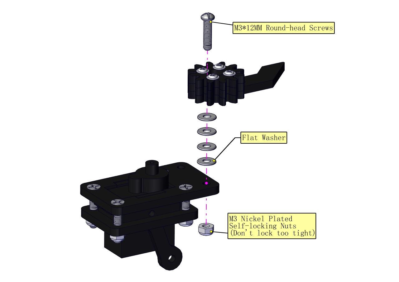
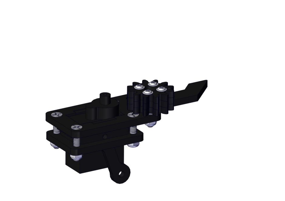
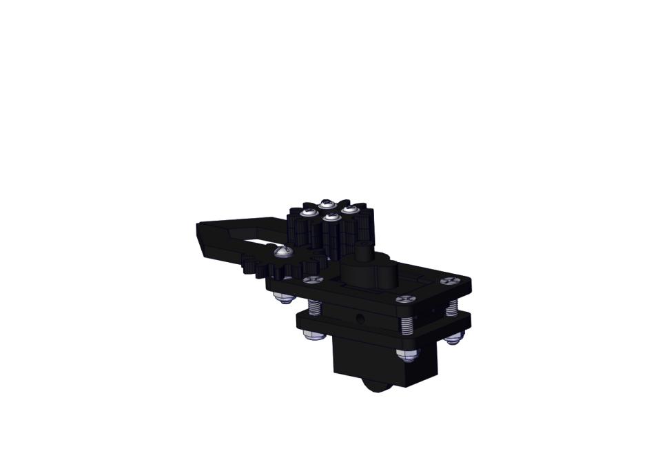
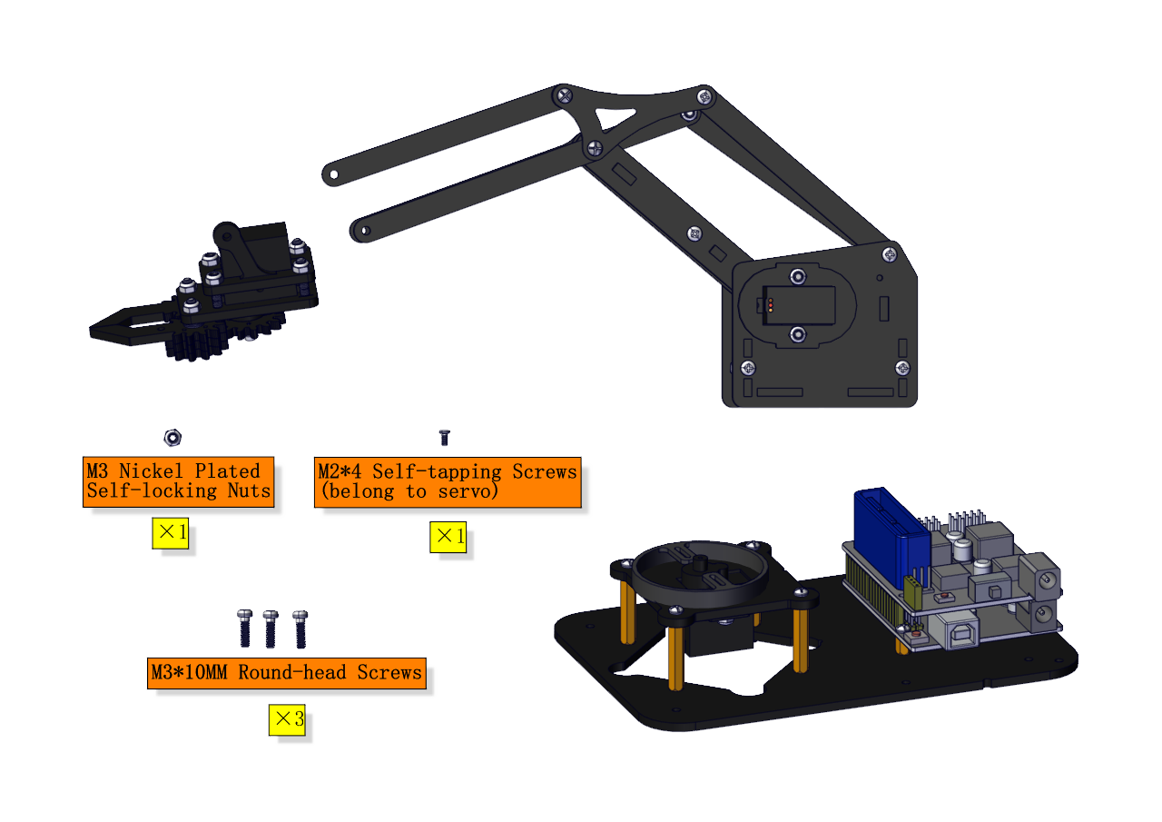
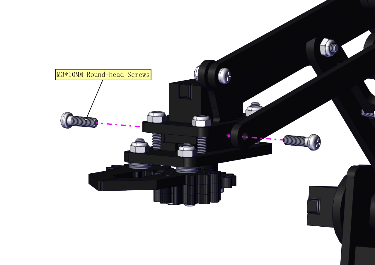
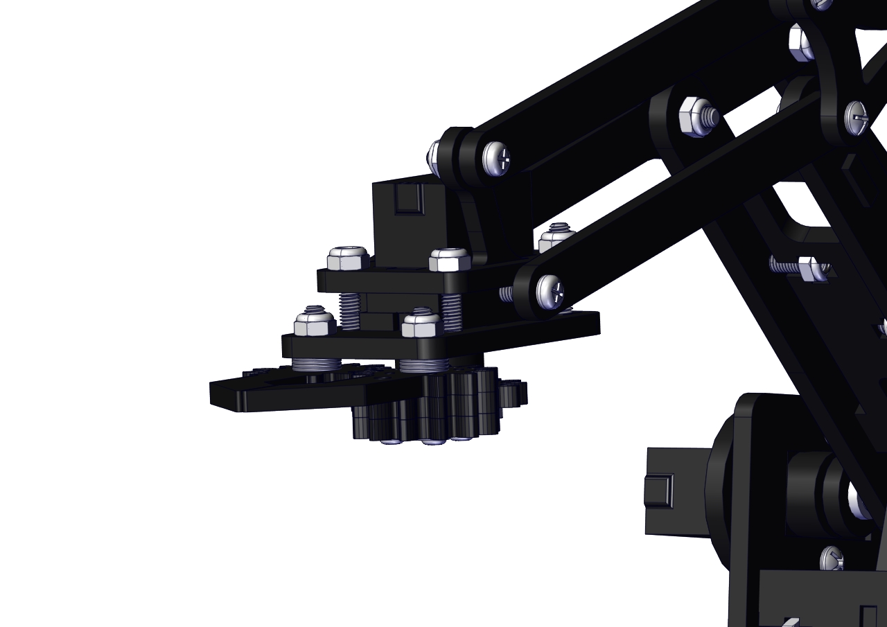
Install the robotic arm:
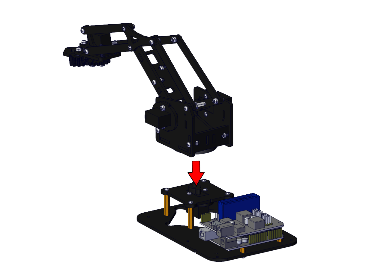
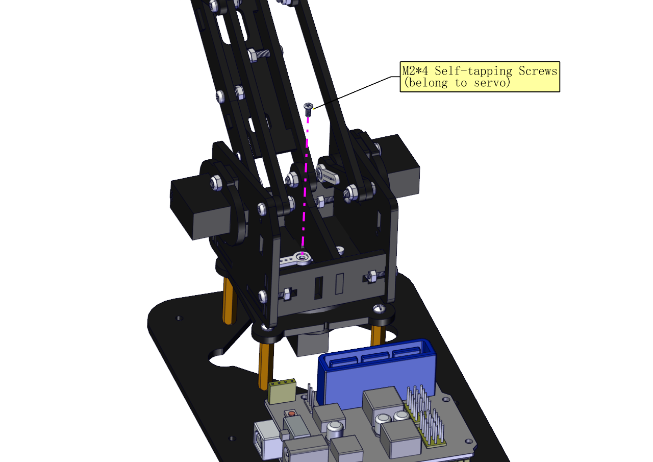
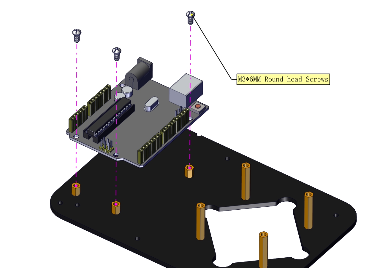
Mount the control part
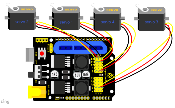
Wiring-up Guide
5. Robot Arm Projects
Project 1: Install Arduino IDE and Driver
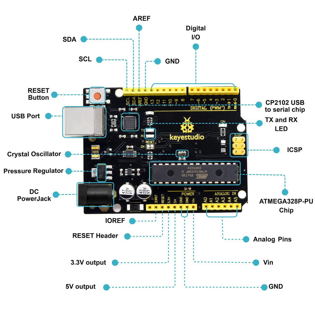
Keyestudio V4.0 Development Board
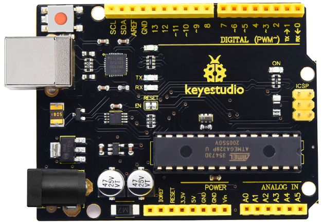
Keyestudio V4.0 development board is an Arduino uno-compatible board, which is based on ATmega328P MCU, and with a cp2102 Chip as a UART-to-USB converter.
1 |
ICSP (In-Circuit Serial Programming) Header |
the AVR, an Arduino micro-program header consisting of MOSI, MISO, SCK, RESET, VCC, and GND. It is often called the SPI (serial peripheral interface) and can be considered an “extension” of the output. In fact, slave the output devices to the SPI bus host. When connecting to PC, program the firmware to ATMEGA328P-PU. |
|---|---|---|
2 |
Power LED Indicator |
Powering the Arduino, LED on means that your circuit board is correctly powered on. If LED is off, connection is wrong. |
3 |
Digital I/O |
Arduino MEGA has 14 digital input/output pins (of which 6 can be used as PWM outputs).These pins can be configured as digital input pin to read the logic value (0 or 1). Or used as digital output pin to drive different modules like LED, relay, etc. Using pinMode(), digitalWrite(), and digitalRead() functions. |
4 |
GND |
GND |
5 |
AREF |
Reference voltage (0-5V) for analog inputs. Used with analogReference(). Configures the reference voltage used for analog input (i.e. the value used as the top of the input range). |
6 |
SDA |
IIC communication pin |
7 |
SCL |
IIC communication pin |
8 |
RESET Button |
You can reset your Arduino board, |
9 |
D13 LED |
There is a built-in LED driven by digital pin 13. When the pin is HIGH value, the LED is on, when the pin is LOW, it’s off. |
10 |
USB Connection |
Arduino board can be powered via USB connector. All you needed to do is connecting the USB port to PC using a USB cable. |
11 |
CP2102 |
USB serial chip, translate the USB signal of computer into serial signal |
12 |
TX LED |
Onboard you can find the label: TX (transmit) When Arduino board communicates via serial port, send the message, TX led flashes. |
13 |
RX LED |
Onboard you can find the label: RX(receive ) When Arduino board communicates via serial port, receive the message, RX led flashes. |
14 |
Crystal Oscillator |
How does Arduino calculate time? by using a crystal oscillator. The number printed on the top of the Arduino crystal is 16.000H9H. It tells us that the frequency is 16,000,000 Hertz or 16MHz. |
15 |
Voltage Regulator |
To control the voltage provided to the Arduino board, as well as to stabilize the DC voltage used by the processor and other components. Convert an external input DC7-12V voltage into DC 5V, then switch DC 5V to the processor and other components. |
16 |
DC Power Jack |
Arduino board can be supplied with an external power DC7-12V from the DC power jack. |
17 |
Microcontroller |
Each Arduino board has its own microcontroller. You can regard it as the brain of your board. The main IC (integrated circuit) on the Arduino is slightly different from the panel pair. Microcontrollers are usually from ATMEL. Before you load a new program on the Arduino IDE, you must know what IC is on your board. This information can be checked at the top of IC. |
18 |
IOREF |
This pin on the board provides the voltage reference with which the microcontroller operates. A properly configured shield can read the IOREF pin voltage and select the appropriate power source or enable voltage translators on the outputs for working with the 5V or 3.3V. |
19 |
RESET Header |
Connect an external button to reset the board. The function is the same as reset button. |
20 |
Power Pin 3V3 |
A 3.3 volt supply generated by the on-board regulator. Maximum current draw is 50 mA. |
21 |
Power Pin 5V |
Provides 5V output voltage |
22 |
Vin |
You can supply an external power input DC7-12V through this pin to Arduino board. |
23 |
Analog Pins |
Onboard has 6 analog inputs, labeled A0 to A5. |
Installing Arduino IDE

Click the link to start learning how to download software, install drivers, upload code, and install library files.
Project 2: 4DOF Rotation and Pin Control
(1)Joint Rotation and Servo Angle Settings
Name |
0° |
180° |
|---|---|---|
Servo 1(baseplate) |
Rotate toward the rightmost |
Rotate toward the leftmost |
Servo 2 (right side) |
Rocker arm connected to Servo 2 draws back |
stretch out |
Servo 3 (left side) |
Rocker arm connected to Servo 3 stretches out |
draw back |
Servo 4 (clamp claw) |
close |
open |
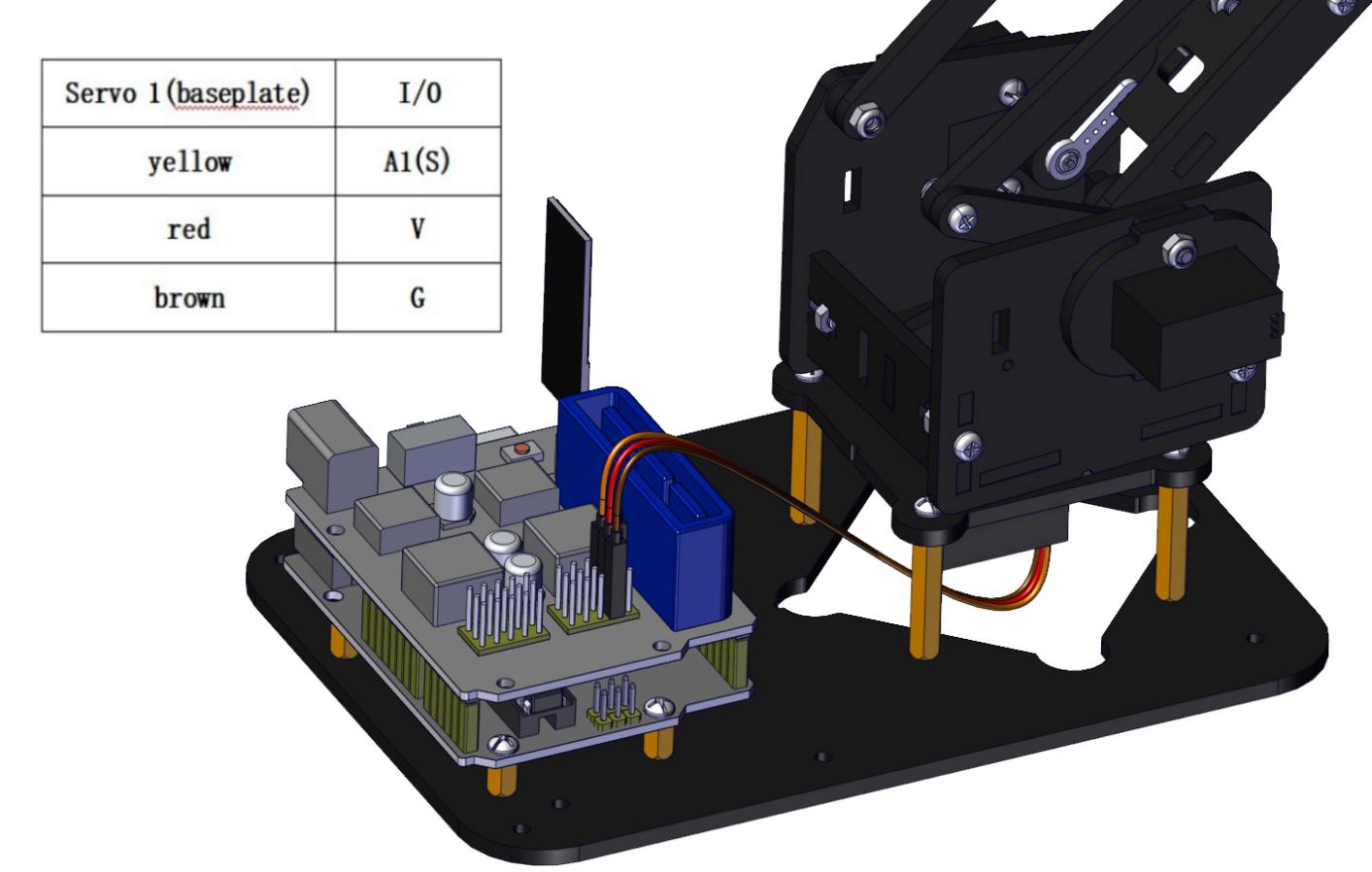
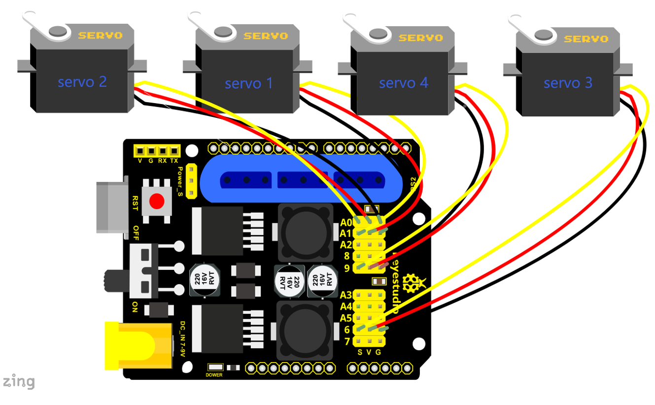
(2)Pin Control
Name |
IO Pin |
|---|---|
Servo 1 (baseplate) |
A1 |
Servo 2 (right side) |
A0 |
Servo 3 (left side) |
6 |
Servo 4 (clamp claw) |
9 |
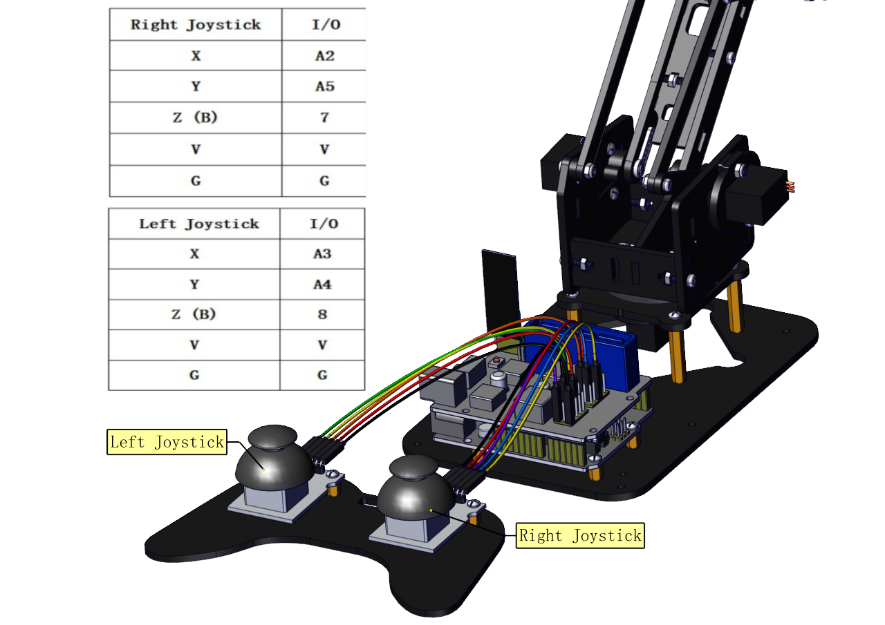
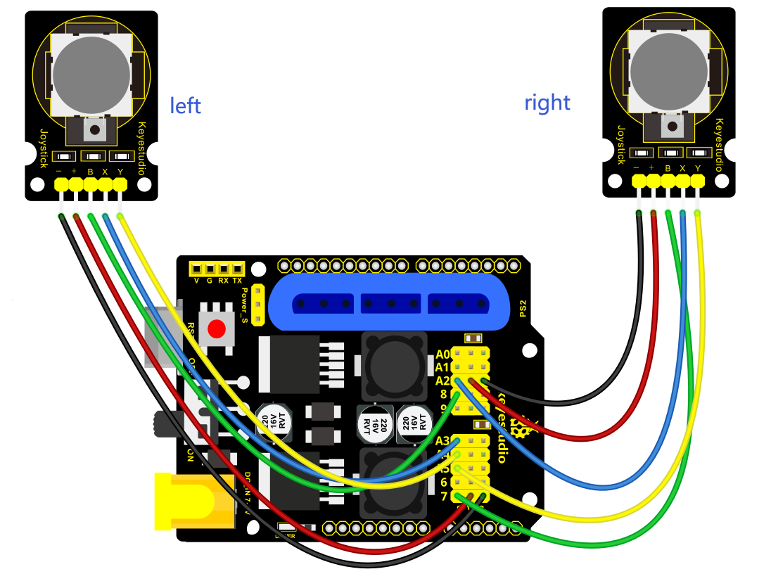
Right Joystick X |
A2 |
Right Joystick Y |
A5 |
Right Joystick Z (B) |
7 |
Left Joystick X |
A3 |
Left Joystick Y |
A4 |
Left Joystick Z(B) |
8 |
D1/DAT of PS2 |
12 |
D0/CMD of PS2 |
11 |
CE/SEL of PS2 |
10 |
CLK of PS2 |
13 |
Project 3: Control the Robot Arm by Joysticks
3.1 Servo Control
Description
In the previous projects, we set the square wave and angles of servos.
Now, we use libraries of servos to control the angle of a servo. We only need to put the servo folder in the libraries folder where the Arduino IDE location is installed, then open the Arduino IDE, the library file will take effect.
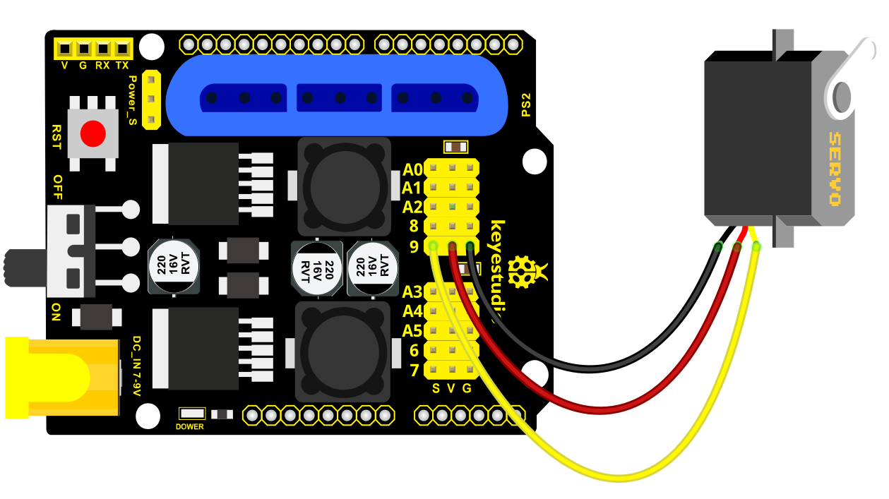
Connection Diagram
Test Code 1:
 #include  <Servo.h >

Servo myservo; // create servo object to control a servo

void setup()

{

Serial.begin(9600);

delay(1000);

}

void loop()

{

myservo.attach(A0); // modify each pin to adjust

myservo.write(0); // angle value

delay(1000);

}
Test Result:
Stack the drive shield onto V4.0 board and connect the servo motor, upload the code, plug in power and press the reset button. Then the servo will automatically rotate to 0°.
Automatic Movement
Description:
In the previous section, you have learned to set the servo angle. In fact, we just need to continually change angles of 4 servo, thus make the 4DOF robot arm operate different motions.
Hookup Guide:
Test Code 2:
 #include  <Servo.h >

Servo myservo1; // create servo object to control a servo

Servo myservo2;

Servo myservo3;

Servo myservo4;

int pos1=80, pos2=60, pos3=130, pos4=0;

void setup()

{

myservo1.attach(A1); // attaches the servo on pin 9 to the servo object

myservo2.attach(A0);

myservo3.attach(6);

myservo4.attach(9);

myservo1.write(pos1);

delay(1000);

myservo2.write(pos2);

myservo3.write(pos3);

myservo4.write(pos4);

delay(1500);

}

void loop()

{

// turn right

for(pos1;pos1 >0;pos1--)

{

myservo1.write(pos1);

delay(5); // delay 5ms(used to adjust the servo speed)

}

delay(1000);

// open the claw

for(pos4;pos4 <100;pos4++)

{

myservo4.write(pos4);

}

delay(1000);

// right servo rotates to 100 degrees

for(pos2;pos2 >50;pos2--)

{

myservo2.write(pos2);

delay(5);

}

// left servo rotates to 5 degrees

for(pos3;pos3 >50;pos3--)

{

myservo3.write(pos3);

delay(5);

}

delay(1500);

// close the claw

for(pos4;pos4 >0;pos4--)

{

myservo4.write(pos4);

}

delay(1000);

// left servo rotates to100 degrees, rocker arm lifts.

for(pos3;pos3 <120;pos3++)

{

myservo3.write(pos3);

delay(5);

}

delay(1000);

// turn to left

for(pos1;pos1 <180;pos1++)

{

myservo1.write(pos1);

delay(5);

}

delay(1000);

// Lower the arm

for(pos3;pos3 >50;pos3--)

{

myservo3.write(pos3);

delay(5);

}

delay(1000);

// open the claw

for(pos4;pos4 <100;pos4++)

{

myservo4.write(pos4);

}

delay(1000);

// lift up the arm

for(pos3;pos3 <120;pos3++)

{

myservo3.write(pos3);

delay(5);

}

delay(1000);

// close the claw

for(pos4;pos4 >0;pos4--)

{

myservo4.write(pos4);

}

delay(1000);

}
Test Result:
Stack the driver shield onto V4.0 board and connect the servo motor, upload well the code., plug in power and press the reset button. Then the robot arm will rotate to right, stretch out the arm, lower and enable claw; then it will withdraw, lift, rotate to left, stretch out, lower and make claw open.
This series of actions will be continuous.
3.2 Read the Joystick Value
Description:
The sensor’s pin X, Y are for analog sensor, so directly read the measured analog value. Pin Z is a digital button, first should set the pin to Input status and then read the measured value 1 (pressed down) or 0 (not press). Check out the value printed on the serial monitor.
Connection Diagram:
Test Code 3:
const int right_X = A2; // define the right X pin to A2

const int right_Y = A5; // define the right Y pin to A5

const int right_key = 7; //define the right key pin to 7(that is the value Z)

const int left_X = A3; //define the left X pin to A3

const int left_Y = A4; // define the left Y pin to A4

const int left_key = 8; //define the left key pin to 8(that is the value Z)

void setup()

{

pinMode(right_key, INPUT); // set the right/left key to INPUT

pinMode(left_key, INPUT);

Serial.begin(9600); // set the baud rate to 9600

}

void loop()

{

int x1,y1,z1; // define the variable, used to save the joystick value it reads

int x2,y2,z2;

x1 = analogRead(right_X); // read the value of right X

y1 = analogRead(right_Y); // read the value of right Y

z1 = digitalRead(right_key); //// read the value of right Z

x2 = analogRead(left_X); // read the value of left X

y2 = analogRead(left_Y); // read the value of left Y

z2 = digitalRead(left_key); // read the value of left Z

Serial.print("right_X = "); // on the serial monitor, print out right_X =

Serial.println(x1 ,DEC); // print out the value of right X and line wrap

Serial.print("right_Y = ");

Serial.println(y1 ,DEC);

//Serial.print("right_key = ");

//Serial.println(z1 ,DEC);

// Serial.println("**********right**********");

/*Serial.print("left_X = ");

Serial.println(x2 ,DEC);

Serial.print("left_Y = ");

Serial.println(y2 ,DEC);

Serial.print("left_key = ");

Serial.println(z2 ,DEC);

Serial.println("*********left***********");*/

delay(200);

}
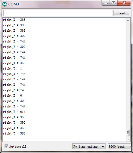
Test Result:
Hook it up and upload well the code. Connect the V4.0 to computer using a USB cable, then open the serial monitor and set the baud rate to 9600, you should see the analog value of the right Joystick pin X,Y.
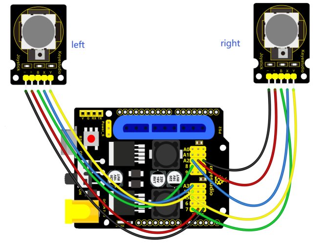
3.3 Dual-Joystick Control
Description:
In the previous section, we have introduced how to use 4 Servo to control the robot arm. Next, combine those two experiments. Use two Joystick modules to control 4DOF robot arm realize different motions.
At first, set the boot posture. The Joystick control is shown as below table.
Right Joystick |
Servo |
Left Joystick |
Servo |
|---|---|---|---|
X1 <50 |
Servo 1 gradually reduces to 0° (push the right joystick to the right, the servo that controls the arm rotation turns right, and stops at 0° ) |
X2 <50 |
Servo 4 gradually reduces to 0° (push the left joystick to the right, the claw is closed) |
X1 >1000 |
Servo 1 gradually increases to 180° (push the right joystick to the left, the servo that controls the arm rotation turns left, and stops at 180° ) |
X2 >1000 |
Servo 4 gradually increases to 180° (push the left joystick to the left, the claw opens) |
Y1 >1000 |
Servo 2 gradually reduces to 0° ( that is, lift up the robot upper arm) |
Y2 >1000 |
Servo 3 gradually reduces to 35° ( that is, stretch out the robot lower arm) |
Y1 <50 |
Servo 2 gradually reduces to 180° ( that is, lower the robot upper arm) |
Y2 <50 |
Servo 3 gradually increases to 180° ( that is, draw back the robot lower arm) |
Hookup Guide:
Test Code 4:
  #include   <Servo.h  > // add the servo libraries

Servo myservo1; // create servo object to control a servo

Servo myservo2;

Servo myservo3;

Servo myservo4;

int pos1=80, pos2=60, pos3=130, pos4=0; // define the variable of 4 servo
angle,and assign the initial value (that is the boot posture angle value)

const int right_X = A2; // define the right X pin to A2

const int right_Y = A5; // define the right Y pin to A5

const int right_key = 7; // define the right key pin to 7(that is the value of
Z)

const int left_X = A3; // define the left X pin to A3

const int left_Y = A4; // define the left X pin to A4

const int left_key = 8; //define the left key pin to 8(that is the value of Z)

int x1,y1,z1; // define the variable, used to save the joystick value it read.

int x2,y2,z2;

void setup()

{

// boot posture

myservo1.write(pos1);

delay(1000);

myservo2.write(pos2);

myservo3.write(pos3);

myservo4.write(pos4);

delay(1500);

pinMode(right_key, INPUT); // set the right/left key to INPUT

pinMode(left_key, INPUT);

Serial.begin(9600); // set the baud rate to 9600

}

void loop()

{

myservo1.attach(A1); // set the control pin of servo 1 to A1

myservo2.attach(A0); // set the control pin of servo 2 to A0

myservo3.attach(6); //set the control pin of servo 3 to D6

myservo4.attach(9); // set the control pin of servo 4 to D9

x1 = analogRead(right_X); //read the right X value

y1 = analogRead(right_Y); // read the right Y value

z1 = digitalRead(right_key); //// read the right Z value

x2 = analogRead(left_X); //read the left X value

y2 = analogRead(left_Y); //read the left Y value

z2 = digitalRead(left_key); // read the left Z value

//delay(5); // lower the speed overall

// claw

zhuazi();

// rotate

zhuandong();

// upper arm

xiaobi();

//lower arm

dabi();

}

//claw

void zhuazi()

{

//claw

if(x2  <50) // if push the left joystick to the right

{

pos4=pos4-2; //current angle of servo 4 subtracts 2(change the value you
subtract, thus change the closed speed of claw)

//Serial.println(pos4);

myservo4.write(pos4); // servo 4 operates the action, claw is gradually closed.

delay(5);

if(pos4  <2) // if pos4 value subtracts to 2, the claw in 37 degrees we have
tested is closed.

{ //(should change the value based on the fact)

pos4=2; // stop subtraction when reduce to 2

}

}

if(x2  >1000) //// if push the left joystick to the left

{

pos4=pos4+8; // current angle of servo 4 plus 8(change the value you plus, thus
change the open speed of claw)

//Serial.println(pos4);

myservo4.write(pos4); // servo 4 operates the motion, the claw gradually opens.

delay(5);

if(pos4  >108) // limit the largest angle when open the claw

{

pos4=108;

}

}

}

//*********************************  *  *  *******************

// turn

void zhuandong()

{

if(x1  <50) // if push the right joystick to the right

{

pos1=pos1-1; //pos1 subtracts 1

myservo1.write(pos1); // servo 1 operates the motion, the arm turns right.

delay(5);

if(pos1  <1) // limit the angle when turn right

{

pos1=1;

}

}

if(x1  >1000) // if push the right joystick to the let

{

pos1=pos1+1; //pos1 plus 1

myservo1.write(pos1); // arm turns left

delay(5);

if(pos1  >180) // limit the angle when turn left

{

pos1=180;

}

}

}

//  *  *  *  *  *  *  *  *  *  *  *  *  *  *  *  *  *  *  *  *  *  *  *  *  *  *  *  *  *  *  *  *  *  *  *  *  *  *  *  *  *  *  *  *  *  *  *  *  *  *  *  *  *  *  *  *  **/

//upper arm

void xiaobi()

{

if(y1>1000) // if push the right joystick upward

{

pos2=pos2-1;

myservo2.write(pos2); // the upper arm will lift

delay(5);

if(pos2  <0) // limit the lifting angle

{

pos2=0;

}

}

if(y1  <50) // if push the right joystick downward

{

pos2=pos2+1;

myservo2.write(pos2); // upper arm will go down

delay(5);

if(pos2  >180) // limit the angle when go down

{

pos2=180;

}

}

}


// lower arm

void dabi()

{

if(y2<50) // if push the left joystick upward

{

pos3=pos3+1;

myservo3.write(pos3); // lower arm will stretch out

delay(5);

if(pos3  >180) // limit the stretched angle

{

pos3=180;

}

}

if(y2  >1000) // if push the left joystick downward

{

pos3=pos3-1;

myservo3.write(pos3); // lower arm will draw back

delay(5);

if(pos3  <35) // limit the retracted angle

{

pos3=35;

}

}

}
Test Result:
Upload the code to main board and stack the shield onto it and wire them up, then 4DOF robot arm will keep the initial position. You can control the robot arm with Joysticks
3.4 Add Memory Function
Memorize One Posture
Description:
In the previous section, use the analog value of pin X,Y of 2 Joystick modules to control the robot arm.
In the following experiment, we add a memory function for the robot arm, making it remember a posture then operate. Set 4 variables for saving the angle value of 4 servos, use the Joystick to control a posture. Press the key Z1 of right Joystick to save the angle value of 4 servos; press the key Z2 of left Joystick to make the servo operate a posture saved in the variable.
Connection Diagram
Test Code 5:
  #include   <Servo.h  > // add servo libraries

Servo myservo1; // create servo object to control a servo

Servo myservo2;

Servo myservo3;

Servo myservo4;

int pos1=80, pos2=60, pos3=130, pos4=0; // define the variable of 4 servo angle
and assign the initial value( that is the boot posture angle value)

const int right_X = A2; // define the right X pin to A2

const int right_Y = A5; // define the right Y pin to A3

const int right_key = 7; // define the right key pin to 7(that is Z value)

const int left_X = A3; // define the left X pin to A3

const int left_Y = A4; // define the left Y pin to A4

const int left_key = 8; // define the left key pin to 8(that is Z value)

int x1,y1,z1; // define the variable, used to save the joystick value.

int x2,y2,z2;

int s1,s2,s3,s4;

void setup()

{

// boot posture

myservo1.write(pos1);

delay(1000);

myservo2.write(pos2);

myservo3.write(pos3);

myservo4.write(pos4);

delay(1500);

pinMode(right_key, INPUT); // set the right/left key to INPUT

pinMode(left_key, INPUT);

Serial.begin(9600); // set the baud rate to 9600

}

void loop()

{

myservo1.attach(A1); // set the control pin of servo 1 to A1

myservo2.attach(A0); // set the control pin of servo 2 to A0

myservo3.attach(6); //set the control pin of servo 3 to D6

myservo4.attach(9); //set the control pin of servo 4 to D9

x1 = analogRead(right_X); // read the right X value

y1 = analogRead(right_Y); // read the right Y value

z1 = digitalRead(right_key); //// read the right key Z value

x2 = analogRead(left_X); // read the left X value

y2 = analogRead(left_Y); //read the left Y value

z2 = digitalRead(left_key); //read the left key Z value

//delay(5); // reduce the speed overall

if(z1==1) // if the right joystick key is pressed

{

delay(10); // delay for eliminating shake

if(z1==1) // judge again if the right key is pressed

{

s1=myservo1.read(); // read the angle value of each servo

s2=myservo2.read();

s3=myservo3.read();

s4=myservo4.read();

}

}

if(z2==1) // if the left key is pressed

{

delay(10);

if(z2==1)

{

pos1=myservo1.read(); // record the angle value of 4 servos in current posture

pos2=myservo2.read();

pos3=myservo3.read();

pos4=myservo4.read();

if(pos1  <s1) // if angle of servo 1 is smaller than variable s1 value

{

while(pos1  <s1) //while loop,rotate the servo to the position of the value
stored in the array.

{

myservo1.write(pos1); // servo 1 operates the motion

pos1++; //pos1 plus 1

delay(5); // delay for 5ms,controlling the rotation speed of servo.

}

}

else // if angle of servo 1 is greater than the value stored in array 1.

{

while(pos1  >s1) //while loop,rotate the servo to the position of the value
stored in the array.

{

myservo1.write(pos1); // servo 1 operates the motion

pos1--; //pos1 subtracts 1

delay(5); // delay for 5ms,controlling the rotation speed of servo.

}

}


// the explanation is the same as servo 1

if(pos2<s2)

{

while(pos2<s2)

{

myservo2.write(pos2);

pos2++;

delay(5);

}

}

else

{

while(pos2>s2)

{

myservo2.write(pos2);

pos2--;

delay(5);

}

}

//*************************************************

// the explanation is the same as servo 1

if(pos3<s3)

{

while(pos3<s3)

{

myservo3.write(pos3);

pos3++;

delay(5);

}

}

else

{

while(pos3>s3)

{

myservo3.write(pos3);

pos3--;

delay(5);

}

}

//*************************************************

// the explanation is the same as servo 1

if(pos4<s4)

{

while(pos4<s4)

{

myservo4.write(pos4);

pos4++;

delay(5);

}

}

else

{

while(pos4>s4)

{

myservo4.write(pos4);

pos4--;

delay(5);

}

}

}

}

//claw

zhuazi();

//turn

zhuandong();

// upper arm

xiaobi();

// lower arm

dabi();

}

//claw

void zhuazi()

{

//claw

if(x2  <50) // if push the left joystick to the right

{

pos4=pos4-2; // current angle of servo 4 subtracts 2(change the value you
subtract, thus change the closed speed of claw)

//Serial.println(pos4);

myservo4.write(pos4); //servo 4 operates the action, claw is gradually closed

delay(5);

if(pos4  <2) // if pos4 value subtracts to 2, the claw in 37 degrees we have
tested is closed.)

{ //(should change the value based on the fact)

pos4=2; // stop subtraction when reduce to 2

}

}

if(x2  >1000) //// if push the left joystick to the left

{

pos4=pos4+8; // current angle of servo 4 plus 8(change the value you plus, thus
change the open speed of claw)

//Serial.println(pos4);

myservo4.write(pos4); // servo 4 operates the motion, the claw gradually opens.

delay(5);

if(pos4  >90) // limit the largest angle when open

{

pos4=90;

}

}

}

//  *  *  *  *  *  *  *  *  *  *  *  *  *  *  *  *  *  *  *  *  *  *  *  *  *  *  *  *  *  *  *  *  *  *  *  *  *  *  *  *  *  *  *  *  *  *  *  *  *  *  *  *  *  *

// turn

void zhuandong()

{

if(x1  <50) // if push the right joystick to the right

{

pos1=pos1-1; //pos1 subtracts 1

myservo1.write(pos1); // servo 1 operates the motion, the arm turns right.

delay(5);

if(pos1  <1) // limit the angle when turn right

{

pos1=1;

}

}

if(x1  >1000) // if push the right joystick to the left

{

pos1=pos1+1; //pos1 plus 1

myservo1.write(pos1); // robot arm turns left

delay(5);

if(pos1  >180) // limit the angle when turn left

{

pos1=180;

}

}

}

//  *  *  *  *  *  *  *  *  *  *  *  *  *  *  *  *  *  *  *  *  *  *  *  *  *  *  *  *  *  *  *  *  *  *  *  *  *  *  *  *  *  *  *  *  *  *  *  *  *  *  *  *  *  *  *  *  *  */

// upper arm

void xiaobi()

{

if(y1  >1000) // if push the right joystick upward

{

pos2=pos2-1;

myservo2.write(pos2); // the upper arm will lift

delay(5);

if(pos2  <0) // limit the lifting angle

{

pos2=0;

}

}

if(y1  <50) // if push the right joystick downward

{

pos2=pos2+1;

myservo2.write(pos2); // the upper arm will go down

delay(5);

if(pos2  >180) // limit the angle when go down

{

pos2=180;

}

}

}

//  *  *  *  *  *  *  *  *  *  *  *  *  *  *  *  *  *  *  *  *  *****************************************/

// lower arm

void dabi()

{

if(y2>1000) // if push the left joystick upward

{

pos3=pos3-1;

myservo3.write(pos3); // the lower arm will stretch out

delay(5);

if(pos3<35) // limit the stretched angle

{

pos3=35;

}

}

if(y2<50) // if push the left joystick downward

{

pos3=pos3+1;

myservo3.write(pos3); // the lower arm will draw back

delay(5);

if(pos3>180) // limit the retracted angle

{

pos3=180;

}

}

}
Test Result:
Stack the shield onto V4.0, wire them up, upload the code, plug in power and press the key Z1 of right Joystick to save the angle value of 4 servos control and press the key Z2 of left Joystick to operate a servo posture saved in the variable.
Memorize Multiple Postures
Description:
In the previous section, we have set the angle of 4 servos to make the robot arm remember and operate a posture. To extend the experiment, next make it remember several postures, at most 10 (you can set it in the code), then make 4DOF robot arm continually operate the posture in memory. That is, make robot arm memorize a group of actions, and you can set the memorizing speed in the code.
Connection Diagram
Test Code 6:
#include <Servo.h> // add the servo libraries

Servo myservo1; // create servo object to control a servo

Servo myservo2;

Servo myservo3;

Servo myservo4;

int pos1=80, pos2=60, pos3=130, pos4=0; // define the variable of 4 servo angle
and assign the initial value( that is the boot posture angle value)

const int right_X = A2; // define the right X pin to A2

const int right_Y = A5; // define the right Y pin to A5

const int right_key = 7; // define the right key pin to 7(that is Z value)

const int left_X = A3; // define the left X pin to A3

const int left_Y = A4; // define the left Y pin to A4

const int left_key = 8; // define the left key pin to 8(that is Z value)

int x1,y1,z1; //define the variable, used to save the joystick value.

int x2,y2,z2;

int s1,s2,s3,s4;

int jiyi1[10]; // define 4 array, separately used to save the angle of four
servo.

int jiyi2[10]; //(array length is 10,namely can save angle data of 0~10 servo
)

int jiyi3[10]; // if need to save more data, just change the number 10 to be
more larger number.

int jiyi4[10];

int i=0; // for loop

int j=0; // save the last value of i

void setup()

{

// boot posture

myservo1.write(pos1);

delay(1000);

myservo2.write(pos2);

myservo3.write(pos3);

myservo4.write(pos4);

delay(1500);

pinMode(right_key, INPUT); // set the right/left key to INPUT

pinMode(left_key, INPUT);

Serial.begin(9600); // set baud rate to 9600

}

void loop()

{

myservo1.attach(A1); // set the control pin of servo 1 to A1

myservo2.attach(A0); // set the control pin of servo 2 to A0

myservo3.attach(6); // set the control pin of servo 3 to D6

myservo4.attach(9); // set the control pin of servo 4 to D9

x1 = analogRead(right_X); // read the right X value

y1 = analogRead(right_Y); // read the right Y value

z1 = digitalRead(right_key); // read the right Z value

x2 = analogRead(left_X); // read the left X value

y2 = analogRead(left_Y); // read the left Y value

z2 = digitalRead(left_key); // read the left Z value

//delay(5); // reduce the speed overall

if(z1==1) // if the right joystick key is pressed

{

delay(10); // delay for eliminating shake

if(z1==1) // judge again if the right key is pressed

{

s1=myservo1.read(); // read the angle value of each servo

delay(100);

Serial.println(s1);

s2=myservo2.read();

delay(100);

Serial.println(s2);

s3=myservo3.read();

delay(100);

Serial.println(s3);

s4=myservo4.read();

delay(100);

Serial.println(s4);

jiyi1[i]=s1; // Save the read servo value to the array sequentially

jiyi2[i]=s2;

jiyi3[i]=s3;

jiyi4[i]=s4;

i++; //i value plus 1

j=i; // assign the last value of i to j

delay(100);

Serial.println(i); // on the serial monitor, print out the value i

}

}

if(z2==1) // if the left joystick key is pressed

{

delay(10);

if(z2==1) // judge again if the left key is pressed

{

i=0; // assign i to 0,prepare for the next memory

pos1 = myservo1.read(); // memorize the angle value of 4 servo posture

pos2 = myservo2.read();

pos3 = myservo3.read();

pos4 = myservo4.read();

for(int k=0;k<j;k++) // loop for j times, perform all actions saved.

{

if(pos1<jiyi1[k]) // if the current servo 1 angle is less than the value stored
in array 1.

{

while(pos1<jiyi1[k]) //while loop, make servo turn to the position of value
stored in the array.

{

myservo1.write(pos1); // servo 1 performs the action

delay(5); // delay 5ms,controlling the servo rotating speed

pos1++; //pos1 plus 1

//Serial.println(pos1);

}

}

else // if the current servo 1 angle is greater than the value stored in array
1.

{

while(pos1>jiyi1[k]) //while loop, make servo turn to the position of value
stored in the array.

{

myservo1.write(pos1); // servo 1 performs the action

delay(5); //delay 5ms,controlling the servo rotating speed

pos1--; //pos1 subtracts 1

//Serial.println(pos1);

}

}

//***************************************************************

//the explanation is the same as the previous servo

if(pos2<jiyi2[k])

{

while(pos2<jiyi2[k])

{

myservo2.write(pos2);

delay(5);

pos2++;

//Serial.println(pos1);

}

}

else

{

while(pos2>jiyi2[k])

{

myservo2.write(pos2);

delay(5);

pos2--;

//Serial.println(pos1);

}

}

//***************************************************************

// the explanation is the same as the previous servo

if(pos3<jiyi3[k])

{

while(pos3<jiyi3[k])

{

myservo3.write(pos3);

delay(5);

pos3++;

//Serial.println(pos1);

}

}

else

{

while(pos3>jiyi3[k])

{

myservo3.write(pos3);

delay(5);

pos3--;

//Serial.println(pos1);

}

}

//***************************************************************

//the explanation is the same as the previous servo

if(pos4<jiyi4[k])

{

while(pos4<jiyi4[k])

{

myservo4.write(pos4);

delay(5);

pos4++;

//Serial.println(pos1);

}

}

else

{

while(pos4>jiyi4[k])

{

myservo4.write(pos4);

delay(5);

pos4--;

//Serial.println(pos1);

}

}

}

}

}

//claw

zhuazi();

//turn

zhuandong();

//upper arm

xiaobi();

// lower arm

dabi();

}

//claw

void zhuazi()

{

//claw

if(x2<50) // if push the left joystick to the right

{

pos4=pos4-2; // angle of servo 4, subtract 2 (change the value you subtract,
thus change the closed speed of claw)

//Serial.println(pos4);

myservo4.write(pos4); // servo 4 operates the motion and claw is gradually
closed.

delay(5);

if(pos4<2) // if pos4 value subtracts to 2, the claw in 37 degrees we have
tested is closed.)

{ //(should change the value based on the fact)

pos4=2; // stop subtraction when reduce to 2

}

}

if(x2>1000) //// if push the left joystick to the left

{

pos4=pos4+8; // current angle of servo 4 plus 8(change the value you plus, thus
change the open speed of claw)

//Serial.println(pos4);

myservo4.write(pos4); // servo 4 operates the action, claw gradually opens.

delay(5);

if(pos4>90) // limit the largest angle opened

{

pos4=90;

}

}

}

//******************************************************

// turn

void zhuandong()

{

if(x1<50) // if push the right joystick to the right

{

pos1=pos1-1; //pos1 subtracts 1

myservo1.write(pos1); // servo 1 operates the motion and robot arm turns right

delay(5);

if(pos1<1) // limit the angle when turn right

{

pos1=1;

}

}

if(x1>1000) // if push the right joystick to the left

{

pos1=pos1+1; //pos1 plus 1

myservo1.write(pos1); // robot arm turns left

delay(5);

if(pos1>180) // limit the angle when turn left

{

pos1=180;

}

}

}

//**********************************************************/

// upper arm

void xiaobi()

{

if(y1>1000) // if push the right joystick upward

{

pos2=pos2-1;

myservo2.write(pos2); // the upper arm will lift

delay(5);

if(pos2<0) // limit the lifting angle

{

pos2=0;

}

}

if(y1<50) // if push the right joystick downward

{

pos2=pos2+1;

myservo2.write(pos2); // the upper arm will go down

delay(5);

if(pos2>180) // limit the declining angle

{

pos2=180;

}

}

}

//*************************************************************/

// lower arm

void dabi()

{

if(y2>1000) // if push the left joystick upward

{

pos3=pos3-1;

myservo3.write(pos3); // the lower arm will stretch out

delay(5);

if(pos3<35) // limit the stretched angle

{

pos3=35;

}

}

if(y2<50) // if push the left joystick downward

{

pos3=pos3+1;

myservo3.write(pos3); // the lower arm will draw back

delay(5);

if(pos3>180) // limit the retracted angle

{

pos3=180;

}

}

}
Test Result:
Stack the shield onto V4.0, wire them up, upload the code, plug in power and press the key Z1 of right Joystick to save the angle value of 4 servos control and press the key Z2 of left Joystick to operate a servo posture saved in the variable.
Memorize Multiple Postures
Description:
In the previous section, we have set the angle of 4 servos to make the robot arm remember and operate a posture. To extend the experiment, next make it remember several postures, at most 10 (you can set it in the code), then make 4DOF robot arm continually operate the posture in memory. That is, make robot arm memorize a group of actions, and you can set the memorizing speed in the code.
Connection Diagram
Test Code 6:
#include <Servo.h>  // add the servo libraries

Servo myservo1;  // create servo object to control a servo

Servo myservo2;

Servo myservo3;

Servo myservo4;

int pos1=80, pos2=60, pos3=130, pos4=0;  //  define the variable of 4 servo angle and assign the initial value( that is the boot posture angle value)


const int right_X = A2; //  define the right X pin to A2

const int right_Y = A5; // define the right Y pin to A5

const int right_key = 7; // define the right key pin to 7(that is Z value)


const int left_X = A3; //  define the left X pin to A3

const int left_Y = A4;  //  define the left Y pin to A4

const int left_key = 8; // define the left key pin to 8(that is Z value)


int x1,y1,z1;  //define the variable, used to save the joystick value.

int x2,y2,z2;

int s1,s2,s3,s4;

int jiyi1[10];  // define 4 array, separately used to save the angle of four servo.

int jiyi2[10];  //(array length is 10,namely can save angle data of 0~10 servo )

int jiyi3[10];  // if need to save more data, just change the number 10 to be more larger number.

int jiyi4[10];

int i=0; // for loop

int j=0; // save the last value of i


void setup()

{

 // boot posture

 myservo1.write(pos1);

 delay(1000);

 myservo2.write(pos2);

 myservo3.write(pos3);

 myservo4.write(pos4);

 delay(1500);


 pinMode(right_key, INPUT);  // set the right/left key to INPUT

 pinMode(left_key, INPUT);

 Serial.begin(9600); //  set baud rate to 9600

}


void loop()

{

 myservo1.attach(A1);  // set the control pin of servo 1 to A1

 myservo2.attach(A0);  // set the control pin of servo 2 to A0

 myservo3.attach(6);  // set the control pin of servo 3 to D6

 myservo4.attach(9);  // set the control pin of servo 4 to D9


 x1 = analogRead(right_X); // read the right X value

 y1 = analogRead(right_Y);  // read the right Y value

 z1 = digitalRead(right_key);  // read the right Z value


 x2 = analogRead(left_X);  // read the left X value

 y2 = analogRead(left_Y);  // read the left Y value

 z2 = digitalRead(left_key);  // read the left Z value

 //delay(5);  // reduce the speed overall

 if(z1==1)  // if the right joystick key is pressed

 {

  delay(10);  // delay for eliminating shake

  if(z1==1)  // judge again if the right key is pressed

  {

   s1=myservo1.read();   // read the angle value of each servo

   delay(100);

   Serial.println(s1);

   s2=myservo2.read();

   delay(100);

   Serial.println(s2);

   s3=myservo3.read();

   delay(100);

   Serial.println(s3);

   s4=myservo4.read();

   delay(100);

   Serial.println(s4);


   jiyi1[i]=s1;  // Save the read servo value to the array sequentially

   jiyi2[i]=s2;

   jiyi3[i]=s3;

   jiyi4[i]=s4;

   i++;   //i value plus 1

   j=i;   // assign the last value of i to j

   delay(100);

   Serial.println(i);  // on the serial monitor, print out the value i

  }

 }


 if(z2==1) // if the left joystick key is pressed

 {

  delay(10);

  if(z2==1)  // judge again if the left key is pressed

  {

   i=0;  // assign i to 0,prepare for the next memory

   pos1 = myservo1.read();   // memorize the angle value of 4 servo posture

   pos2 = myservo2.read();

   pos3 = myservo3.read();

   pos4 = myservo4.read();


   for(int k=0;k<j;k++)  // loop for j times, perform all actions saved.

   {

    if(pos1<jiyi1[k])   // if the current servo 1 angle is less than the value stored in array 1.

    {

     while(pos1<jiyi1[k])  //while loop, make servo turn to the position of value stored in the array.

     {

      myservo1.write(pos1);  // servo 1 performs the action

      delay(5);   // delay 5ms,controlling the servo rotating speed

      pos1++;  //pos1 plus 1

      //Serial.println(pos1);

     }

    }

    else   // if the current servo 1 angle is greater than the value stored in array 1.

    {

     while(pos1>jiyi1[k])   //while loop, make servo turn to the position of value stored in the array.

     {

      myservo1.write(pos1);  // servo 1 performs the action

      delay(5);   //delay 5ms,controlling the servo rotating speed

      pos1--;   //pos1 subtracts 1

      //Serial.println(pos1);

     }

    }

//***************************************************************

 //the explanation is the same as the previous servo

    if(pos2<jiyi2[k])

    {

     while(pos2<jiyi2[k])

     {

      myservo2.write(pos2);

      delay(5);

      pos2++;

      //Serial.println(pos1);

     }

    }

    else

    {

     while(pos2>jiyi2[k])

     {

      myservo2.write(pos2);

      delay(5);

      pos2--;

      //Serial.println(pos1);

     }

    }

 //***************************************************************

 // the explanation is the same as the previous servo


    if(pos3<jiyi3[k])

    {

     while(pos3<jiyi3[k])

     {

      myservo3.write(pos3);

      delay(5);

      pos3++;

      //Serial.println(pos1);

     }

    }

    else

    {

     while(pos3>jiyi3[k])

     {

      myservo3.write(pos3);

      delay(5);

      pos3--;

      //Serial.println(pos1);

     }

    }

 //***************************************************************

 //the explanation is the same as the previous servo


    if(pos4<jiyi4[k])

    {

     while(pos4<jiyi4[k])

     {

      myservo4.write(pos4);

      delay(5);

      pos4++;

      //Serial.println(pos1);

     }

    }

    else

    {

     while(pos4>jiyi4[k])

     {

      myservo4.write(pos4);

      delay(5);

      pos4--;

      //Serial.println(pos1);

     }

    }

   }

  }

 }


 //claw

 zhuazi();

 //turn

 zhuandong();

 //upper arm

 xiaobi();

 // lower arm

 dabi();

}


//claw

void zhuazi()

{

  //claw

 if(x2<50) // if push the left joystick to the right

 {

   pos4=pos4-2;  // angle of servo 4, subtract 2 (change the value you subtract, thus change the closed speed of claw)

   //Serial.println(pos4);

   myservo4.write(pos4);  // servo 4 operates the motion and claw is gradually closed.

   delay(5);

   if(pos4<2)  // if pos4 value subtracts to 2, the claw in 37 degrees we have tested is closed.)

   {       //(should change the value based on the fact)

    pos4=2;  // stop subtraction when reduce to 2

   }

  }

 if(x2>1000) //// if push the left joystick to the left

 {

   pos4=pos4+8; // current angle of servo 4 plus 8(change the value you plus, thus change the open speed of claw)

   //Serial.println(pos4);

   myservo4.write(pos4); //  servo 4 operates the action, claw gradually opens.

   delay(5);

   if(pos4>90)  // limit the largest angle opened

   {

    pos4=90;

   }

 }

}

//******************************************************

 // turn

void zhuandong()

{

 if(x1<50)  // if push the right joystick to the right

 {

  pos1=pos1-1;  //pos1 subtracts 1

  myservo1.write(pos1);  // servo 1 operates the motion and robot arm turns right

  delay(5);

  if(pos1<1)  // limit the angle when turn right

  {

   pos1=1;

  }

 }

 if(x1>1000)  // if push the right joystick to the left

 {

  pos1=pos1+1;  //pos1 plus 1

  myservo1.write(pos1);  // robot arm turns left

  delay(5);

  if(pos1>180)  // limit the angle when turn left

  {

   pos1=180;

  }

 }

}


//************************************************

// upper arm

void xiaobi()

{

  if(y1>1000) // if push the right joystick upward

 {

  pos2=pos2-1;

  myservo2.write(pos2); // the upper arm will lift

  delay(5);

  if(pos2<0)  // limit the lifting angle

  {

   pos2=0;

  }

 }

 if(y1<50)  // if push the right joystick downward

 {

  pos2=pos2+1;

  myservo2.write(pos2);  // the upper arm will go down

  delay(5);

  if(pos2>180)  // limit the declining angle

  {

   pos2=180;

  }

 }

}


//*************************************************************/

// lower arm

void dabi()

{

 if(y2>1000)  // if push the left joystick upward

 {

  pos3=pos3-1;

  myservo3.write(pos3);  // the lower arm will stretch out

  delay(5);

  if(pos3<35)  // limit the stretched angle

  {

   pos3=35;

  }

 }


 if(y2<50)  // if push the left joystick downward

 {

  pos3=pos3+1;

  myservo3.write(pos3);  // the lower arm will draw back

  delay(5);

  if(pos3>180)  // limit the retracted angle

  {

   pos3=180;

  }

 }

}
Test Result:
Wire it up, stack the shield onto V4.0, upload the code. Powered on, press the key Z1 of right Joystick to save the angle value of 4 servos. Press down the key Z1 to memorize different postures, at most 10 postures in the code. If need to memorize more postures, you can set it in the code. When memorizing successfully, press down the key Z2 of left Joystick to make the robot arm carry out several postures stored successively.
Move the thumbsticks and press the button of right thumbstick, then move them and press the right button again. That indicates that actions of the arm are memorized. Next, you can press the left button to perform actions saved.
Memorize Several Postures And Loop
Description:
In the previous section, we have introduced how to make 4DOF robot arm to memorize and perform a group of posture. Furthermore, let’s extend one more loop function. When the robot arm performs all the memorized actions, it will not stop, and continue to repeat those actions.
In the following experiment, press the key Z1, 4DOF robot arm will exit the looping action. Press the key Z1 again, start to memorize the posture, after that, press the key Z2 to loop the memorized actions.
Hookup Guide:
Test Code 7:
#include <Servo.h> // add the servo libraries

Servo myservo1; // create servo object to control a servo

Servo myservo2;

Servo myservo3;

Servo myservo4;

int pos1=80, pos2=60, pos3=130, pos4=0; // define the variable of 4 servo angle
and assign the initial value( that is the boot posture angle value)

const int right_X = A2; // define the right X pin to A2

const int right_Y = A5; // define the right Y pin to A5

const int right_key = 7; // define the right key pin to 7(that is Z value)

const int left_X = A3; //define the left X pin to A3

const int left_Y = A4; // define the left Y pin to A4

const int left_key = 8; // define the left key pin to 8(that is Z value)

int x1,y1,z1; // define the variable, used to save the joystick value.

int x2,y2,z2;

int s1,s2,s3,s4;

int jiyi1[20]; //define 4 array, separately used to save the angle of four
servo.

int jiyi2[20]; // (array length is 20,namely can save angle data of 0~20
servo)

int jiyi3[20]; //if need to save more data, just change the number 20 to be more
larger number.

int jiyi4[20];

int i=0; // for loop

int j=0; // save the last value of i

void setup()

{

// boot posture

myservo1.write(pos1); //turn servo 1 to 90 degrees

delay(1000);

myservo2.write(pos2); // turn servo 2 to 90 degrees

myservo3.write(pos3); // turn servo 3 to 120 degrees

myservo4.write(pos4); // turn servo 4 to 35 degrees

delay(1500);

pinMode(right_key, INPUT); // set the right/left key to INOUT

pinMode(left_key, INPUT);

Serial.begin(9600); // set the baud rate to 9600

}

void loop()

{

myservo1.attach(A1); // set the control pin of servo 1 to A1

myservo2.attach(A0); // set the control pin of servo 2 to A0

myservo3.attach(6); //set the control pin of servo 3 to D6

myservo4.attach(9); // set the control pin of servo 4 to D9

x1 = analogRead(right_X); // read the right X value

y1 = analogRead(right_Y); //read the right Y value

z1 = digitalRead(right_key); //read the right Z value

x2 = analogRead(left_X); // read the left X value

y2 = analogRead(left_Y); // read the left Y value

z2 = digitalRead(left_key); // read the left Z value

//delay(5); // delay, used to reduce the joystick value read, that is reduce the
whole speed.

if(z1==1) // if the joystick right key is pressed

{

delay(10); // delay for eliminating shake

if(z1==1) // judge again if the right key is pressed

{

s1=myservo1.read(); // read the angle value of servo 1 and assign it to s1

delay(100);

Serial.println(s1); // print out the angle value of servo 1 on the serial
monitor

s2=myservo2.read(); // read the angle value of servo 2 and assign it to s2

delay(100);

Serial.println(s2);

s3=myservo3.read(); // read the angle value of servo 3 and assign it to s3

delay(100);

Serial.println(s3);

s4=myservo4.read(); // read the angle value of servo 4 and assign it to s4

delay(100);

Serial.println(s4);

jiyi1[i]=s1; // Save the read servo value to the array sequentially

jiyi2[i]=s2;

jiyi3[i]=s3;

jiyi4[i]=s4;

i++; //i plus 1

j=i; // assign the last value of i to j

delay(100); // delay 100ms

Serial.println(i); // print out the value i

}

}

if(z2==1) // if the left joystick key is pressed

{

delay(10); // delay for eliminating shake

if(z2==1) //judge again if the left key is pressed

{

pos1 = myservo1.read(); // memorize the angle value of 4 servo posture

pos2 = myservo2.read();

pos3 = myservo3.read();

pos4 = myservo4.read();

while(z2==1) // loop, make the arm repeat the action.

{

for(int k=1;k<j;k++) //for loop, perform all the stored actions.

{

if(pos1<jiyi1[k]) // if the current servo 1 angle is less than the value stored
in array 1.

{

while(pos1<jiyi1[k]) //while loop, make servo turn to the position of value
stored in the array.

{

myservo1.write(pos1); //servo 1 performs the action

delay(5); //delay 5ms,controlling the servo rotating speed.

pos1++; //pos1 plus 1

//Serial.println(pos1);

}

}

else //if the current servo 1 angle is greater than the value stored in array 1.

{

while(pos1>jiyi1[k]) //while loop, make servo turn to the position of value
stored in the array.

{

myservo1.write(pos1); //servo 1 performs the action

delay(5); //delay 5ms,controlling the servo rotating speed.

pos1--; //pos1 subtracts 1

//Serial.println(pos1);

}

}

//***************************************************************

//the explanation is the same as the previous servo.

if(pos2<jiyi2[k])

{

while(pos2<jiyi2[k])

{

myservo2.write(pos2);

delay(5);

pos2++;

//Serial.println(pos1);

}

}

else

{

while(pos2>jiyi2[k])

{

myservo2.write(pos2);

delay(5);

pos2--;

//Serial.println(pos1);

}

}

//*********************************************

//the explanation is the same as the previous servo.

if(pos3<jiyi3[k])

{

while(pos3<jiyi3[k])

{

myservo3.write(pos3);

delay(5);

pos3++;

//Serial.println(pos1);

}

}

else

{

while(pos3>jiyi3[k])

{

myservo3.write(pos3);

delay(5);

pos3--;

//Serial.println(pos1);

}

}

//*********************************************

//the explanation is the same as the previous servo.

if(pos4<jiyi4[k])

{

while(pos4<jiyi4[k])

{

myservo4.write(pos4);

delay(5);

pos4++;

//Serial.println(pos1);

}

}

else

{

while(pos4>jiyi4[k])

{

myservo4.write(pos4);

delay(5);

pos4--;

//Serial.println(pos1);

}

}

}

//************************************************************

// for exiting the loop

z1 = digitalRead(right_key); // read the right Z value

if(z1==1) // if the right key is pressed

{

delay(10); //eliminate the shake

if(z1==1) // if the key z1 is pressed

{

pos1=jiyi1[(j-1)]; // assign the last angle value saved in array to pos

pos2=jiyi2[(j-1)]; // for exiting the loop, still access to joystick control.

pos3=jiyi3[(j-1)];

pos4=jiyi4[(j-1)];

i=0; // assign i as 0,prepare for saving the angle value using array

z2=0; // assign z2 as 0,for exiting the while loop

break; //exit the current loop

}

}

//********************************************************

}

}

}

//claw

zhuazi();

//turn

zhuandong();

//upper arm

xiaobi();

//lower arm

dabi();

}

//claw

void zhuazi()

{

//claw

if(x2<50) // if push the left joystick to the right

{

pos4=pos4-2; // angle of servo 4, subtract 2 (change the value you subtract,
thus change the closed speed of claw)

//Serial.println(pos4);

myservo4.write(pos4); // servo 4 operates the motion and claw is gradually
closed.

delay(5);

if(pos4<2) // if pos4 value subtracts to 2, the claw in 37 degrees we have
tested is closed.)

{ //(should change the value based on the fact)

pos4=2; //stop subtraction when reduce to 2

}

}

if(x2>1000) ////if push the left joystick to the left

{

pos4=pos4+8; //current angle of servo 4 plus 8(change the value you plus, thus
change the open speed of claw)

//Serial.println(pos4);

myservo4.write(pos4); // servo 4 operates the action, claw gradually opens.

delay(5);

if(pos4>90) //limit the largest angle opened

{

pos4=90;

}

}

}

//******************************************************

//turn

void zhuandong()

{

if(x1<50) //if push the right joystick to the right

{

pos1=pos1-1; //pos1 subtracts 1

myservo1.write(pos1); // servo 1 performs the action, the robot arm turns right.

delay(5);

if(pos1<1) // limit the right turning angle

{

pos1=1;

}

}

if(x1>1000) // if push the right joystick to the left

{

pos1=pos1+1; //pos1 plus 1

myservo1.write(pos1); //the robot arm turns left.

delay(5);

if(pos1>180) //limit the left turning angle

{

pos1=180;

}

}

}

//**********************************************************/

// upper arm

void xiaobi()

{

if(y1>1000) // if push the right joystick upward

{

pos2=pos2-1;

myservo2.write(pos2); // the robot arm will lift

delay(5);

if(pos2<0) // limit the lifting angle

{

pos2=0;

}

}

if(y1<50) // if push the right joystick downward

{

pos2=pos2+1;

myservo2.write(pos2); // the robot arm will go down

delay(5);

if(pos2>180) // limit the declining angle

{

pos2=180;

}

}

}

//*************************************************************/

// lower arm

void dabi()

{

if(y2>1000) // if push the left joystick upward

{

pos3=pos3-1;

myservo3.write(pos3); // the lower arm will stretch out

delay(5);

if(pos3<35) // limit the stretched angle

{

pos3=35;

}

}

if(y2<50) // if push the right joystick downward

{

pos3=pos3+1;

myservo3.write(pos3); // the lower arm will draw back

delay(5);

if(pos3>180) // limit the retraction angle

{

pos3=180;

}

}

}
Test Result:
Wire it up, stack the shield onto V4.0, upload the code. Powered on, press the key Z1 of right Joystick to save the angle value of 4 servos. Press down the key Z1 to memorize different postures, at most 10 postures in the code. If need to memorize more postures, can set it in the code.
When memorizing successfully, press down the key Z2 of left Joystick to make the robot arm carry out several postures stored successively, looping.
Long press the key Z1, 4DOF robot arm will exit the looping action. Press the key Z1 again, start to memorize the posture, after that, press the key Z2 to loop the memorized actions.
Move the thumbsticks and press the button of right thumbstick, then move them and press the right button again. That indicates that actions of the arm are memorized. Next, you can press the left button to perform actions saved.
Project 4: BT-controlled Robot Arm
Principle of BT Control
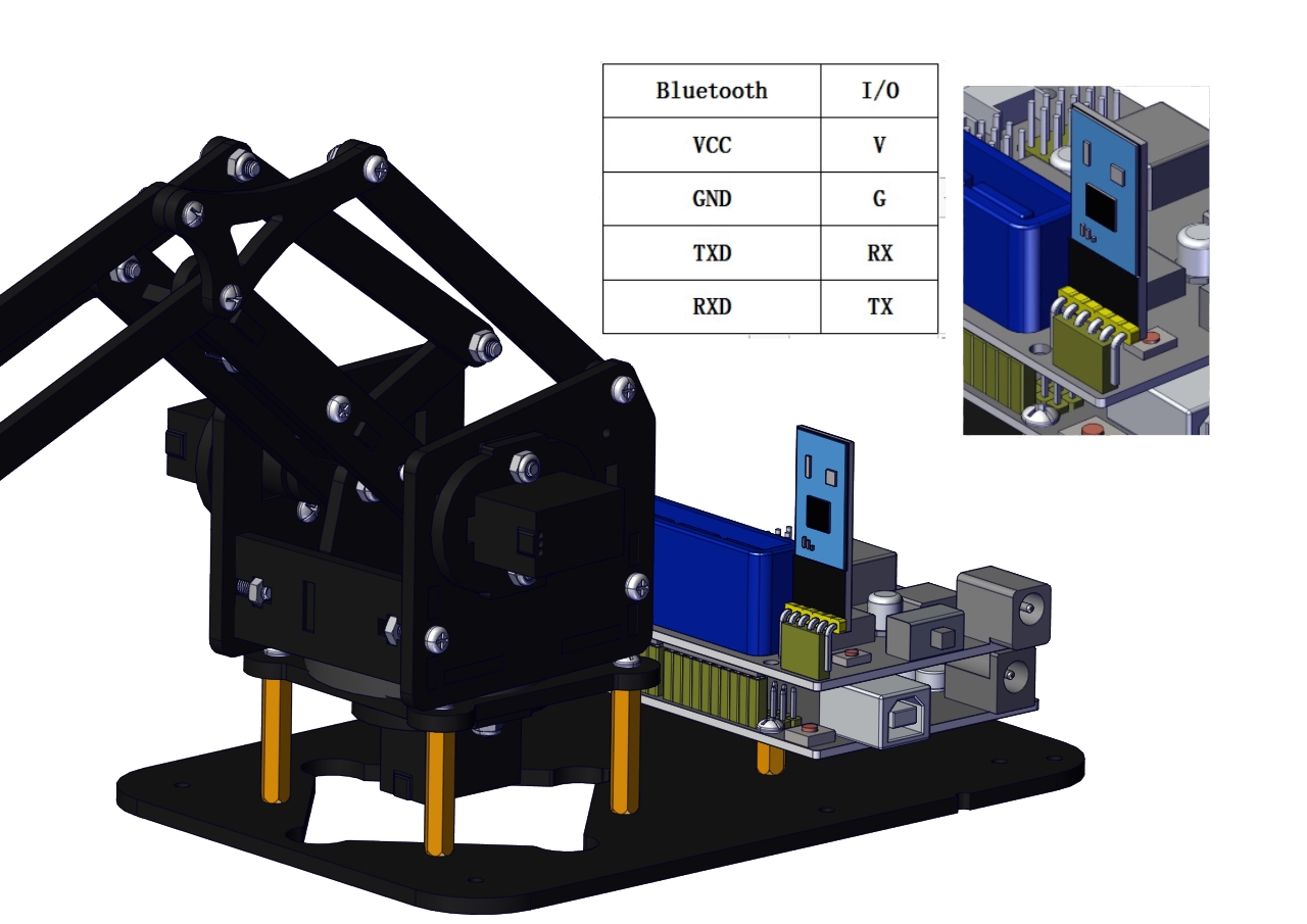
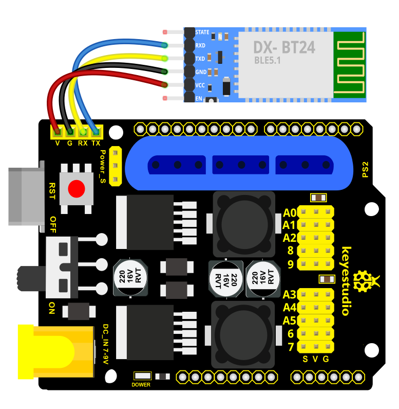
Bluetooth technology is a wireless standard technology that can realize short-distance data exchange between fixed equipment, mobile equipment andpersonal area network (UHF radio waves in the ISM band of 2.4-2.485GHz). In the kit, we equip with the BT-24 Bluetooth module. BT-24 Bluetooth module supports Android and IOS system.
In the experiment, we default the BT-24 Bluetooth module as the slave and the mobile phone as the master.We especially design APP to control robotic arm(Android /IOS system).
Specification
Bluetooth protocol: Bluetooth Specification V5.1 BLE
Working distance: In an open environment, achieve 40m ultra-long distance communication
Operating frequency: 2.4GHz ISM band
Communication interface: UART
Bluetooth certification: in line with FCC CE ROHS REACH certification standards
Serial port parameters: 9600, 8 data bits, 1 stop bit, invalid bit, no flow control
Power: 5V DC
Operating temperature: –10 to +65 degrees Celsius
Bluetooth Control Key Test
Description
Next, we are going to introduce the use method for BT-24 Bluetooth module. To easily use the BT-24 Bluetooth module to control the robot arm, we particularly design the APP control. Shown below.
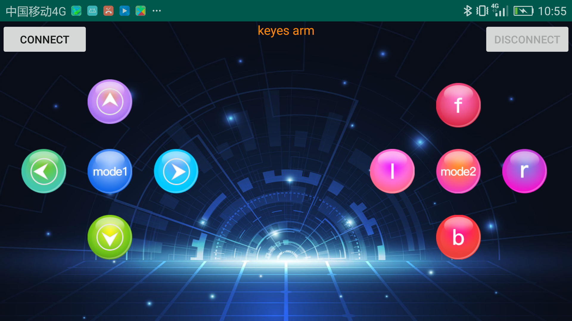
There are 10 control keys on the App. When connect well the HC-06 Bluetooth module to Android phone using our APP, press the control key, Android phone will receive a corresponding value.
When programming, you can set the function for the corresponding value. So in the experiment, we will test each key to get the corresponding value.
Installation Steps for Android system:
APP for Android mobile:
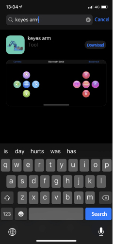
Enter google play,search “keyes arm”.
https://play.google.com/store/apps/details?id=com.keyestudio.keyes_arm_123
Note: Allow APP to access “location” in settings of your cellphone when connecting to Bluetooth module, otherwise, Bluetooth may not be connected.
This are operating steps as below, the interface for Android and ios system is same.
Android System:
Download and install
 ,the
interface shown below:
,the
interface shown below:Upload code and power on, Led of Bluetooth module blinks. Start Bluetooth and open App to click “CONNECT” to connect.
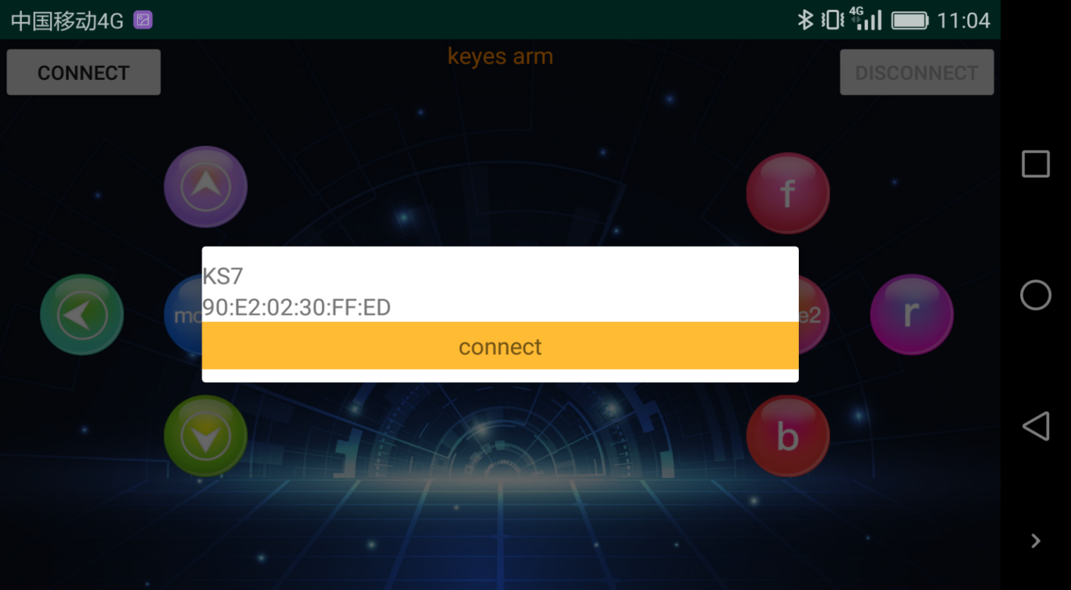
Upload code on control board, after power-on, LED blinks on Bluetooth module. Start Bluetooth and open App to click “connect”, Bluetooth is connected.

For IOS system:
Open App Store

Search “keyes arm”on APP Store,then click “downlaod”.
Special Note: Remove the Bluetooth module please, when uploading the Test Code. Otherwise, the program will fail to upload. After uploading the Test Code, then connect the Bluetooth and Bluetooth module to pair.
Connection Diagram
Test Code
void setup()

{

Serial.begin(9600); // set the serial baud rate to 9600

}

void loop()

{

char val; // define a variable, used to receive the value read from Bluetooth.

if(Serial.available()) // if receive the value

{

val = Serial.read(); // assign the value read to val

Serial.println(val);

}

}
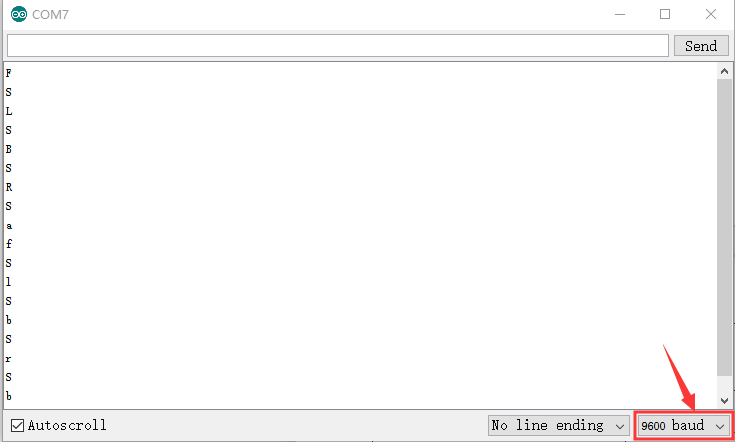
After connecting Bluetooth module, open serial port monitor to set baud rate to
Press control keys on App, the serial port prints out the corresponding control character. As shown below:
Test Result:
The functions of control keys:
|
Connect APP to bt-24 Bluetooth module |
|
|
Turn off Bluetooth |
|
|
Press to send“F” Release to send“S” |
Left servo goes front Left servo stops motion |
|
Press to send “L” Release to send“S” |
Clamp claw opens Clamp claw stops |
|
Mode 1 |
|
|
Press to send “R” Release to send“S” |
Clamp claw closes Clamp claw stops |
|
Press to send “B” Release to send“S” |
Left Servo draws back Left Servo stops motion |
|
Press to send “f” Release to send“S” |
Right servo stretches out Right servo stops motion |
|
Press to send “l” Release to send“S” |
The base servo turns left Base servo stops |
|
Mode 2 |
—————— |
|
Press to send “r” Release to send“S” |
Base Servo turns right Base Servo stops |
|
Press to send “b” Release to send“S” |
Right Servo draws back Right Servo stops |


Bluetooth Controls the Robotic Arm
Description
We introduced the control method of the 4-DOF robot arm and bt-24 Bluetooth module. In this experiment, we’ll control 4DOF robotic arm movement via APP.
Note: After uploading test code successfully, unplug the USB data cable and power up via external power supply and control 4 DOF robot arm movement via APP.
Connection Diagram
Test Code
#include <Servo.h> // add the servo libraries

Servo myservo1; // create servo object to control a servo

Servo myservo2;

Servo myservo3;

Servo myservo4;

int pos1=80, pos2=60, pos3=130, pos4=0; // define the variable of 4 servo angle
and assign the initial value( that is the boot posture angle value)

char val;

char val2;

void setup()

{

// boot posture

myservo1.write(pos1);

delay(1000);

myservo2.write(pos2);

myservo3.write(pos3);

myservo4.write(pos4);

delay(1500);

Serial.begin(9600); // set the baud rate to 9600

}

void loop()

{

myservo1.attach(A1); // set the control pin of servo 1 to A1

myservo2.attach(A0); // set the control pin of servo 2 to A0

myservo3.attach(6); // set the control pin of servo 3 to D6

myservo4.attach(9); // set the control pin of servo 4 to D9

if(Serial.available()) // if receive the data

{

val=Serial.read(); // read the received data

val2=val; //Give the value of val to val2

Serial.println(val);

switch(val)

{

case 'L': T_left(); break; // execute the corresponding function when receive
the value

case 'R': T_right(); break;

case 'f': RF(); break;

case 'b': rb(); break;

case 'F': ZK(); break;

case 'B': ZB(); break;

case 'l': LF(); break;

case 'r': lb(); break;

case 'S': servo_stop(); break; //stop instruction

}

}

else

{

switch(val2) //When the button is pressed and not released,

{ //"else" is executed because Bluetooth does not send characters,

// and the value of val2 is the value of the previously pressed button,

//so the command of pressing the button will be repeated

case 'L': T_left(); break; // execute the corresponding function when receive
the value

case 'R': T_right(); break;

case 'f': RF(); break;

case 'b': rb(); break;

case 'F': ZK(); break;

case 'B': ZB(); break;

case 'l': LF(); break;

case 'r': lb(); break;

case 'S': servo_stop(); break; //stop instruction

}

}

}

//**************************************************

// turn left

void T_left()

{

pos1=pos1+1;

myservo1.write(pos1);

delay(5);

if(pos1>180)

{

pos1=180;

}

}

//turn right

void T_right()

{

pos1=pos1-1;

myservo1.write(pos1);

delay(5);

if(pos1<1)

{

pos1=1;

}

}

//********************************************

//open the claw

void ZK()

{

pos4=pos4-2;

Serial.println(pos4);

myservo4.write(pos4);

delay(5);

if(pos4<2)

{

pos4=0;

}

}

// close the claw

void ZB()

{

pos4=pos4+8;

Serial.println(pos4);

myservo4.write(pos4);

delay(5);

if(pos4>108)

{

pos4=108;

}

}

//******************************************

// the upper arm will lift up

void RF()

{

pos2=pos2-1;

myservo2.write(pos2);

delay(5);

if(pos2<0)

{

pos2=0;

}

}

// the upper arm will go down

void rb()

{

pos2=pos2+1;

myservo2.write(pos2);

delay(5);

if(pos2>180)

{

pos2=180;

}

}

//***************************************

// the lower arm will stretch out

void lb()

{

pos3=pos3+1;

myservo3.write(pos3);

delay(5);

if(pos3>180)

{

pos3=180;

}

}

// the lower arm will draw back

void LF()

{

pos3=pos3-1;

myservo3.write(pos3);

delay(5);

if(pos3<35)

{

pos3=35;

}

}

void servo_stop()

{

myservo1.write(pos1);

myservo2.write(pos2);

myservo3.write(pos3);

myservo4.write(pos4);

}
Test Result:
Upload the code, connect it up and power on, after connecting the Bluetooth APP, press the key to control the robot arm do commanded motions.
Project 5: PS2-controlled Robot Arm (Extension)
5.1 PS2 Joypad Key Test
Description:
On the drive shield there is a PS2 Joystick connector, which is easy for you to control the 4DOF robot arm using the PS2 Joypad. But you need to purchase it by yourself because the PS2 Joypad is not included in the kit.
When use the PS2 Joypad to control the robot arm, first need to get the corresponding character of each key on the PS2 Joypad.
So this experiment will help you test the character of each key on the PS2 Joypad.
After connecting the Joypad, should upload the test program on Arduino IDE. But before testing, should place the PS2X_lib folder inside the libraries folder of Arduino IDE directory.
Uploading the code, open the serial monitor, connect the PS2 Joypad. When press down the key, you should see the corresponding character on the monitor.
Test Code 10:
#include <PS2X_lib.h>  //for v1.6

PS2X ps2x; // create PS2 Controller Class

//right now, the library does NOT support hot pluggable controllers, meaning
//you must always either restart your Arduino after you conect the controller,
//or call config_gamepad(pins) again after connecting the controller.
int error = 0;
byte type = 0;
byte vibrate = 0;

void setup(){
 Serial.begin(57600);

 //CHANGES for v1.6 HERE!!! **************PAY ATTENTION*************

 error = ps2x.config_gamepad(13,11,10,12, true, true);   //setup pins and settings:  GamePad(clock, command, attention, data, Pressures?, Rumble?) check for error

 if(error == 0){
   Serial.println("Found Controller, configured successful");
   Serial.println("Try out all the buttons, X will vibrate the controller, faster as you press harder;");
  Serial.println("holding L1 or R1 will print out the analog stick values.");
  Serial.println("Go to www.billporter.info for updates and to report bugs.");
 }

  else if(error == 1)
   Serial.println("No controller found, check wiring, see readme.txt to enable debug. visit www.billporter.info for troubleshooting tips");

  else if(error == 2)
   Serial.println("Controller found but not accepting commands. see readme.txt to enable debug. Visit www.billporter.info for troubleshooting tips");

  else if(error == 3)
   Serial.println("Controller refusing to enter Pressures mode, may not support it. ");

   //Serial.print(ps2x.Analog(1), HEX);

   type = ps2x.readType();
     switch(type) {
       case 0:
        Serial.println("Unknown Controller type");
       break;
       case 1:
        Serial.println("DualShock Controller Found");
       break;
       case 2:
         Serial.println("GuitarHero Controller Found");
       break;
     }

}

void loop(){
   /* You must Read Gamepad to get new values
   Read GamePad and set vibration values
   ps2x.read_gamepad(small motor on/off, larger motor strenght from 0-255)
   if you don't enable the rumble, use ps2x.read_gamepad(); with no values

   you should call this at least once a second
   */


 if(error == 1) //skip loop if no controller found
  return;

 if(type == 2){ //Guitar Hero Controller

   ps2x.read_gamepad();          //read controller

   if(ps2x.ButtonPressed(GREEN_FRET))
     Serial.println("Green Fret Pressed");
   if(ps2x.ButtonPressed(RED_FRET))
     Serial.println("Red Fret Pressed");
   if(ps2x.ButtonPressed(YELLOW_FRET))
     Serial.println("Yellow Fret Pressed");
   if(ps2x.ButtonPressed(BLUE_FRET))
     Serial.println("Blue Fret Pressed");
   if(ps2x.ButtonPressed(ORANGE_FRET))
     Serial.println("Orange Fret Pressed");


    if(ps2x.ButtonPressed(STAR_POWER))
     Serial.println("Star Power Command");

    if(ps2x.Button(UP_STRUM))          //will be TRUE as long as button is pressed
     Serial.println("Up Strum");
    if(ps2x.Button(DOWN_STRUM))
     Serial.println("DOWN Strum");


    if(ps2x.Button(PSB_START))                   //will be TRUE as long as button is pressed
         Serial.println("Start is being held");
    if(ps2x.Button(PSB_SELECT))
         Serial.println("Select is being held");


    if(ps2x.Button(ORANGE_FRET)) // print stick value IF TRUE
    {
        Serial.print("Wammy Bar Position:");
        Serial.println(ps2x.Analog(WHAMMY_BAR), DEC);
    }
 }

 else { //DualShock Controller

    ps2x.read_gamepad(false, vibrate);          //read controller and set large motor to spin at 'vibrate' speed

    if(ps2x.Button(PSB_START))                   //will be TRUE as long as button is pressed
         Serial.println("Start is being held");
    if(ps2x.Button(PSB_SELECT))
         Serial.println("Select is being held");


     if(ps2x.Button(PSB_PAD_UP)) {         //will be TRUE as long as button is pressed
       Serial.print("Up held this hard: ");
       Serial.println(ps2x.Analog(PSAB_PAD_UP), DEC);
      }
      if(ps2x.Button(PSB_PAD_RIGHT)){
       Serial.print("Right held this hard: ");
        Serial.println(ps2x.Analog(PSAB_PAD_RIGHT), DEC);
      }
      if(ps2x.Button(PSB_PAD_LEFT)){
       Serial.print("LEFT held this hard: ");
        Serial.println(ps2x.Analog(PSAB_PAD_LEFT), DEC);
      }
      if(ps2x.Button(PSB_PAD_DOWN)){
       Serial.print("DOWN held this hard: ");
     Serial.println(ps2x.Analog(PSAB_PAD_DOWN), DEC);
      }


      vibrate = ps2x.Analog(PSAB_BLUE);        //this will set the large motor vibrate speed based on
                                              //how hard you press the blue (X) button

    if (ps2x.NewButtonState())               //will be TRUE if any button changes state (on to off, or off to on)
    {


        if(ps2x.Button(PSB_L3))
         Serial.println("L3 pressed");
        if(ps2x.Button(PSB_R3))
         Serial.println("R3 pressed");
        if(ps2x.Button(PSB_L2))
         Serial.println("L2 pressed");
        if(ps2x.Button(PSB_R2))
         Serial.println("R2 pressed");
        if(ps2x.Button(PSB_GREEN))
         Serial.println("Triangle pressed");

    }


    if(ps2x.ButtonPressed(PSB_RED))             //will be TRUE if button was JUST pressed
         Serial.println("Circle just pressed");

    if(ps2x.ButtonReleased(PSB_PINK))             //will be TRUE if button was JUST released
         Serial.println("Square just released");

    if(ps2x.NewButtonState(PSB_BLUE))            //will be TRUE if button was JUST pressed OR released
         Serial.println("X just changed");


    if(ps2x.Button(PSB_L1) || ps2x.Button(PSB_R1)) // print stick values if either is TRUE
    {
        Serial.print("Stick Values:");
        Serial.print(ps2x.Analog(PSS_LY), DEC); //Left stick, Y axis. Other options: LX, RY, RX
        Serial.print(",");
        Serial.print(ps2x.Analog(PSS_LX), DEC);
        Serial.print(",");
        Serial.print(ps2x.Analog(PSS_RY), DEC);
        Serial.print(",");
        Serial.println(ps2x.Analog(PSS_RX), DEC);
    }


 }


 delay(50);

}
Test Result:
Stack the drive shield onto V4.0 and upload the code. Connecting the PS2 Joypad, open the serial monitor and set the baud rate to 57600. When press down the key or push the rocker, you should see the corresponding character showed on the monitor.
5.2 PS2 Joypad Control
Description:
In the previous section, we have showed how to use Joystick module to control the robot arm. It is almost the same for you to control the 4DOF robot arm using the PS2 Joypad.
PS2 Joystick Control
Right Joystick |
Robot Arm |
Left Joystick |
Robotic Claw |
|---|---|---|---|
Push to the right side |
Rotate to right |
Push to the right side |
close |
Push to the left side |
Rotate to left |
Push to the left side |
open |
Push forward |
The small arm will lift |
Push forward |
The large arm will move forward |
Push back |
The small arm will lower |
Push back |
The large arm will move back |
Connection Diagram
Test Code
#include <PS2X_lib.h>

PS2X ps2x; // create PS2 Controller Class

//right now, the library does NOT support hot pluggable controllers, meaning

//you must always either restart your Arduino after you connect the controller,

//or call config_gamepad(pins) again after connecting the controller.

int error = 0;

byte vibrate = 0;

#include <Servo.h> // add the servo libraries

Servo myservo1; // create servo object to control a servo

Servo myservo2;

Servo myservo3;

Servo myservo4;

int pos1=80, pos2=60, pos3=130, pos4=0; // define the variable of 4 servo angle
and assign the initial value( that is the boot posture angle value)

void setup(){

Serial.begin(57600);

// boot posture

myservo1.write(pos1);

delay(1000);

myservo2.write(pos2);

myservo3.write(pos3);

myservo4.write(pos4);

delay(1500);

error = ps2x.config_gamepad(13,11,10,12); //setup GamePad(clock, command,
attention, data) pins, check for error

if(error == 0){

Serial.println("Found Controller, configured successful");

Serial.println("Try out all the buttons, X will vibrate the controller, faster
as you press harder;");

Serial.println("holding L1 or R1 will print out the analog stick values.");

Serial.println("Go to www.billporter.info for updates and to report bugs.");

}

else if(error == 1)

Serial.println("No controller found, check wiring, see readme.txt to enable
debug. visit www.billporter.info for troubleshooting tips");

else if(error == 2)

Serial.println("Controller found but not accepting commands. see readme.txt to
enable debug. Visit www.billporter.info for troubleshooting tips");

//Serial.print(ps2x.Analog(1), HEX);

ps2x.enableRumble(); //enable rumble vibration motors

ps2x.enablePressures(); //enable reading the pressure values from the buttons.

}

void loop(){

/* You must Read Gamepad to get new values

Read GamePad and set vibration values

ps2x.read_gamepad(small motor on/off, larger motor strenght from 0-255)

if you don't enable the rumble, use ps2x.read_gamepad(); with no values

you should call this at least once a second

*/

myservo1.attach(A1); // set the control pin of servo 1 to A1

myservo2.attach(A0); // set the control pin of servo 2 to A0

myservo3.attach(6); // set the control pin of servo 3 to D6

myservo4.attach(9); // set the control pin of servo 4 to D9

if(error != 0)

return;

ps2x.read_gamepad(false, vibrate); //read controller and set large motor to spin
at 'vibrate' speed

if(ps2x.Button(PSB_START)) //will be TRUE as long as button is pressed

Serial.println("Start is being held");

if(ps2x.Button(PSB_SELECT))

Serial.println("Select is being held");

if(ps2x.Button(PSB_PAD_UP)) { //will be TRUE as long as button is pressed

Serial.print("Up held this hard: ");

Serial.println(ps2x.Analog(PSAB_PAD_UP), DEC);

}

if(ps2x.Button(PSB_PAD_RIGHT)){

Serial.print("Right held this hard: ");

Serial.println(ps2x.Analog(PSAB_PAD_RIGHT), DEC);

}

if(ps2x.Button(PSB_PAD_LEFT)){

Serial.print("LEFT held this hard: ");

Serial.println(ps2x.Analog(PSAB_PAD_LEFT), DEC);

}

if(ps2x.Button(PSB_PAD_DOWN)){

Serial.print("DOWN held this hard: ");

Serial.println(ps2x.Analog(PSAB_PAD_DOWN), DEC);

}

vibrate = ps2x.Analog(PSAB_BLUE); //this will set the large motor vibrate speed
based on

//how hard you press the blue (X) button

if (ps2x.NewButtonState()) //will be TRUE if any button changes state (on to
off, or off to on)

{

if(ps2x.Button(PSB_R3))

Serial.println("R3 pressed");

if(ps2x.Button(PSB_L3))

Serial.println("L3 pressed");

if(ps2x.Button(PSB_L2))

Serial.println("L2 pressed");

if(ps2x.Button(PSB_R2))

Serial.println("R2 pressed");

if(ps2x.Button(PSB_GREEN))

Serial.println("Triangle pressed");

}

if(ps2x.ButtonPressed(PSB_RED)) //will be TRUE if button was JUST pressed

Serial.println("Circle just pressed");

if(ps2x.ButtonReleased(PSB_PINK)) //will be TRUE if button was JUST released

Serial.println("Square just released");

if(ps2x.NewButtonState(PSB_BLUE)) //will be TRUE if button was JUST pressed OR
released

Serial.println("X just changed");

//rotate

zhuandong();

//claw

zhuazi();

//upper arm

dabi();

//forearm

xiaobi();

if(ps2x.Button(PSB_L1) || ps2x.Button(PSB_R1)) // print stick values if either
is TRUE

{

Serial.print("Stick Values:");

Serial.print(ps2x.Analog(PSS_LY), DEC); //Left stick, Y axis. Other options: LX,
RY, RX

Serial.print(",");

Serial.print(ps2x.Analog(PSS_LX), DEC);

Serial.print(",");

Serial.print(ps2x.Analog(PSS_RY), DEC);

Serial.print(",");

Serial.println(ps2x.Analog(PSS_RX), DEC);

}

delay(5);

}

//********************************************************************

// turn

void zhuandong()

{

//turn right

if(ps2x.Analog (PSS_RX) > 200) // if push the right joystick to the right

{

//Serial.println(ps2x.Analog(PSS_RX), DEC);

pos1=pos1-1; //pos1 subtracts 1

myservo1.write(pos1); // servo 1 executes the action, the arm will turn right.

// delay(5);

if(pos1<1) // limit the right turning angle

{

pos1=1;

}

}

// turn left

if(ps2x.Analog (PSS_RX) < 50) // if push the right joystick to the left

{

//Serial.println(ps2x.Analog(PSS_RX), DEC);

pos1=pos1+1; //pos1 plus 1

myservo1.write(pos1); // the arm turns left

// delay(5);

if(pos1>180) // limit the left turning angle

{

pos1=180;

}

}

}

//**********************************************************************

// upper arm

void xiaobi()

{

//upper arm front

if(ps2x.Analog(PSS_RY)<50) // if push the right joystick upward

{

pos2=pos2-1;

myservo2.write(pos2); // the upper arm will lift

delay(5);

if(pos2<0) // limit the lifting angle

{

pos2=0;

}

}

//upper arm back

if(ps2x.Analog(PSS_RY)>200) // if push the right joystick downward

{

pos2=pos2+1;

myservo2.write(pos2); // the upper arm will go down

delay(5);

if(pos2>180) // limit the declining angle

{

pos2=180;

}

}

}

//***************************************************************

void zhuazi()

{

// close the claw

if(ps2x.Analog(PSS_LX)>220) // if push the left joystick to the right

{

pos4=pos4-1;

Serial.println(pos4);

myservo4.write(pos4); // servo 4 carries out the action and the claw is
gradually closed.

delay(5);

if(pos4<0) // if pos4 value subtracts to 37, the claw in 37 degrees we have
tested is closed.)

{

pos4=0;

}

}

// open the claw

if(ps2x.Analog(PSS_LX)<10) // if push the left joystick to the left

{

pos4=pos4+8;

Serial.println(pos4);

myservo4.write(pos4); // servo 4 carries out the action and the claw is
gradually opened

delay(5);

if(pos4>108) // limit the maximum opening angle

{

pos4=108;

}

}

}

//*********************************************************

void dabi()

{

// lower arm front

if(ps2x.Analog(PSS_LY)>200) // if push the left joystick upward

{

pos3=pos3+1;

myservo3.write(pos3); // the lower arm will stretch out

delay(5);

if(pos3>180) // limit the stretched angle

{

pos3=180;

}

}

if(ps2x.Analog(PSS_LY)<10) //if push the left joystick downward

{

pos3=pos3-1;

myservo3.write(pos3); // the lower arm will draw back

delay(5);

if(pos3<35) // limit the retracted angle

{

pos3=35;

}

}

}
Test Result
Control the robotic arm with PS2 joypad.
5.3 PS2 Controlling Posture Memory
Description
In the previous experiment, we have showed how to use Joystick module to memorize several postures. Now we replace the joystick module with PS2 Joypad. Press the Z1 button to memorize the postures of the arm. If you want to memorize more, you can set in the code. After that, press the Z2 button to perform the saved actions of the arm
Connection Diagram
Test Code12
#include <PS2X_lib.h>

#include <Servo.h> // add the servo libraries

Servo myservo1; // create servo object to control a servo

Servo myservo2;

Servo myservo3;

Servo myservo4;

int pos1=80, pos2=60, pos3=130, pos4=0; // define the variable of 4 servo angle
and assign the initial value( that is the boot posture angle value)

PS2X ps2x; // create PS2 Controller Class

//right now, the library does NOT support hot pluggable controllers, meaning

//you must always either restart your Arduino after you conect the controller,

//or call config_gamepad(pins) again after connecting the controller.

int error = 0;

byte vibrate = 0;

int s1,s2,s3,s4;

int jiyi1[20]; // define four array, separately used to save the angle of 4
servos.

int jiyi2[20];

int jiyi3[20];

int jiyi4[20];

int i=0;

int j=0;

void setup()

{

Serial.begin(57600);

// boot posture

myservo1.write(pos1);

delay(1000);

myservo2.write(pos2);

myservo3.write(pos3);

myservo4.write(pos4);

delay(1500);

error = ps2x.config_gamepad(13,11,10,12); //setup GamePad(clock, command,
attention, data) pins, check for error

if(error == 0){

Serial.println("Found Controller, configured successful");

Serial.println("Try out all the buttons, X will vibrate the controller, faster
as you press harder;");

Serial.println("holding L1 or R1 will print out the analog stick values.");

Serial.println("Go to www.billporter.info for updates and to report bugs.");

}

else if(error == 1)

Serial.println("No controller found, check wiring, see readme.txt to enable
debug. visit www.billporter.info for troubleshooting tips");

else if(error == 2)

Serial.println("Controller found but not accepting commands. see readme.txt to
enable debug. Visit www.billporter.info for troubleshooting tips");

//Serial.print(ps2x.Analog(1), HEX);

ps2x.enableRumble(); //enable rumble vibration motors

ps2x.enablePressures(); //enable reading the pressure values from the buttons.

}

void loop()

{

myservo1.attach(A1); // set the control pin of servo 1 to A1

myservo2.attach(A0); // set the control pin of servo 2 to A0

myservo3.attach(6); // set the control pin of servo 3 to D6

myservo4.attach(9); // set the control pin of servo 4 to D9

if(error != 0)

return;

ps2x.read_gamepad(false, vibrate); //read controller and set large motor to spin
at 'vibrate' speed

if(ps2x.Button(PSB_START)) //will be TRUE as long as button is pressed

Serial.println("Start is being held");

if(ps2x.Button(PSB_SELECT))

Serial.println("Select is being held");

if(ps2x.Button(PSB_PAD_UP)) { //will be TRUE as long as button is pressed

Serial.print("Up held this hard: ");

Serial.println(ps2x.Analog(PSAB_PAD_UP), DEC);

}

if(ps2x.Button(PSB_PAD_RIGHT)){

Serial.print("Right held this hard: ");

Serial.println(ps2x.Analog(PSAB_PAD_RIGHT), DEC);

}

if(ps2x.Button(PSB_PAD_LEFT)){

Serial.print("LEFT held this hard: ");

Serial.println(ps2x.Analog(PSAB_PAD_LEFT), DEC);

}

if(ps2x.Button(PSB_PAD_DOWN)){

Serial.print("DOWN held this hard: ");

Serial.println(ps2x.Analog(PSAB_PAD_DOWN), DEC);

}

vibrate = ps2x.Analog(PSAB_BLUE); //this will set the large motor vibrate speed
based on

//how hard you press the blue (X) button

if (ps2x.NewButtonState()) //will be TRUE if any button changes state (on to
off, or off to on)

{

if(ps2x.Button(PSB_R3))

{

//Serial.println("R3 pressed");

// record

s1=myservo1.read();

delay(100);

Serial.println(s1);

s2=myservo2.read();

delay(100);

Serial.println(s2);

s3=myservo3.read();

delay(100);

Serial.println(s3);

s4=myservo4.read();

delay(100);

Serial.println(s4);

jiyi1[i]=s1; // save the servo value read in the array sequentially

jiyi2[i]=s2;

jiyi3[i]=s3;

jiyi4[i]=s4;

i++;

j=i;

// delay(100);

Serial.println(i);

}

if(ps2x.Button(PSB_L3))

{

//Serial.println("L3 pressed");

i=0;

//执行

pos1 = myservo1.read();

pos2 = myservo2.read();

pos3 = myservo3.read();

pos4 = myservo4.read();

for(int k=0;k<j;k++) //for loop, to execute all the stored actions

{

if(pos1<jiyi1[k]) //if the current servo 1 angle is less than the value stored
in array 1.

{

while(pos1<jiyi1[k]) //while loop, make servo turn to the position of value
stored in the array.

{

myservo1.write(pos1); // servo 1 executes the action

delay(5); // delay 5ms,controlling the rotating speed of servo

pos1++;

//Serial.println(pos1);

}

}

else //if the current servo 1 angle is greater than the value stored in array 1.

{

while(pos1>jiyi1[k]) //while loop, make servo turn to the position of value
stored in the array.

{

myservo1.write(pos1); // servo 1 executes the action

delay(5); //delay 5ms,controlling the rotating speed of servo

pos1--;

//Serial.println(pos1);

}

//**********************************************

// the same analysis as the previous servo

if(pos2<jiyi2[k])

{

while(pos2<jiyi2[k])

{

myservo2.write(pos2);

delay(5);

pos2++;

//Serial.println(pos1);

}

}

else

{

while(pos2>jiyi2[k])

{

myservo2.write(pos2);

delay(5);

pos2--;

//Serial.println(pos1);

}

}

//*****************************************************

//the same analysis

if(pos3<jiyi3[k])

{

while(pos3<jiyi3[k])

{

myservo3.write(pos3);

delay(5);

pos3++;

//Serial.println(pos1);

}

}

else

{

while(pos3>jiyi3[k])

{

myservo3.write(pos3);

delay(5);

pos3--;

//Serial.println(pos1);

}

}

//*****************************************************

//the same analysis

if(pos4<jiyi4[k])

{

while(pos4<jiyi4[k])

{

myservo4.write(pos4);

delay(5);

pos4++;

//Serial.println(pos1);

}

}

else

{

while(pos4>jiyi4[k])

{

myservo4.write(pos4);

delay(5);

pos4--;

//Serial.println(pos1);

}

}

}

}

}

if(ps2x.Button(PSB_L2))

Serial.println("L2 pressed");

if(ps2x.Button(PSB_R2))

Serial.println("R2 pressed");

if(ps2x.Button(PSB_GREEN))

Serial.println("Triangle pressed");

}

if(ps2x.ButtonPressed(PSB_RED)) //will be TRUE if button was JUST pressed

Serial.println("Circle just pressed");

if(ps2x.ButtonReleased(PSB_PINK)) //will be TRUE if button was JUST released

Serial.println("Square just released");

if(ps2x.NewButtonState(PSB_BLUE)) //will be TRUE if button was JUST pressed OR
released

Serial.println("X just changed");

// turn

zhuandong();

// claw

zhuazi();

// lower arm

dabi();

// upper arm

xiaobi();

if(ps2x.Button(PSB_L1) || ps2x.Button(PSB_R1)) // print stick values if either
is TRUE

{

Serial.print("Stick Values:");

Serial.print(ps2x.Analog(PSS_LY), DEC); //Left stick, Y axis. Other options: LX,
RY, RX

Serial.print(",");

Serial.print(ps2x.Analog(PSS_LX), DEC);

Serial.print(",");

Serial.print(ps2x.Analog(PSS_RY), DEC);

Serial.print(",");

Serial.println(ps2x.Analog(PSS_RX), DEC);

}

delay(5);

}

//********************************************************************

// turn

void zhuandong()

{

//turn right

if(ps2x.Analog (PSS_RX) > 200) // if push the right joystick to the right

{

//Serial.println(ps2x.Analog(PSS_RX), DEC);

pos1=pos1-1; //pos1 subtracts 1

myservo1.write(pos1); // servo 1 carries out the action and the arm will turn
right

// delay(5);

if(pos1<1) // limit the right turning angle

{

pos1=1;

}

}

//left-handed rotation

if(ps2x.Analog (PSS_RX) < 50) //if push the right joystick to the left

{

//Serial.println(ps2x.Analog(PSS_RX), DEC);

pos1=pos1+1; //pos1 plus 1

myservo1.write(pos1); // the arm will turn left

// delay(5);

if(pos1>180) // limit the left turning angle

{

pos1=180;

}

}

}

//**********************************************************************

// upper arm

void xiaobi()

{

//upper arm front

if(ps2x.Analog(PSS_RY)<50) // if push the right joystick upward

{

pos2=pos2-1;

myservo2.write(pos2); // the upper arm will lift up

delay(5);

if(pos2<0) // limit the lifting angle

{

pos2=0;

}

}

// upper arm back

if(ps2x.Analog(PSS_RY)>200) //if push the right joystick downward

{

pos2=pos2+1;

myservo2.write(pos2); // the upper arm will go down

delay(5);

if(pos2>180) // limit the declining angle

{

pos2=180;

}

}

}

//***************************************************************

void zhuazi()

{

// close the claw

if(ps2x.Analog(PSS_LX)>220) // if push the left joystick to the right

{

pos4=pos4-1;

Serial.println(pos4);

myservo4.write(pos4); // servo 4 carries out the action and the claw is
gradually closed.

delay(5);

if(pos4<0) // if pos4 value reduces to 37(the claw we test in 37degrees is
closed)

{

pos4=0;

}

}

// open the claw

if(ps2x.Analog(PSS_LX)<10) // if push the left joystick to the left

{

pos4=pos4+8;

Serial.println(pos4);

myservo4.write(pos4); // servo 4 carries out the action and the claw is
gradually opened

delay(5);

if(pos4>108) // limit the maximum angle opened

{

pos4=108;

}

}

}

//*********************************************************

void dabi()

{

// lower arm front

if(ps2x.Analog(PSS_LY)>200) // if push the left joystick upward

{

pos3=pos3+1;

myservo3.write(pos3); // the lower arm will stretch out

delay(5);

if(pos3>180) // limit the stretched angle

{

pos3=180;

}

}

if(ps2x.Analog(PSS_LY)<10) // if push the left joystick downward

{

pos3=pos3-1;

myservo3.write(pos3); //the lower arm will retract

delay(5);

if(pos3<35) // limit the retracted angle

{

pos3=35;

}

}

}
Test Result
Move the PS2 rocker to control robot arm, press the button of the PS2 rocker to record its posture, and move the joystick again and press the button of the PS2 rocker to memorize the posture. Next, press the left button of the PS2 joypad to perform postures.
5.4 PS2 Controls Posture Memory and Loop
Description:
In the previous experiment, we have showed how to use Joystick module to control the robot arm memorize several postures and loop. Now we replace the Joystick module with the PS2 Joypad. The program is almost the same.
Move the thumbsticks and press the button of the right thumbstick, then move them and press the right button again. That indicates that actions of the arm are memorized. Next, you can press the left button to perform actions saved.
Connection Diagram:
Test Code13
#include <PS2X_lib.h>

#include <Servo.h> // add the servo libraries

Servo myservo1; // create servo object to control a servo

Servo myservo2;

Servo myservo3;

Servo myservo4;

int pos1=80, pos2=60, pos3=130, pos4=0; // define the variable of 4 servo angle
and assign the initial value( that is the boot posture angle value)

PS2X ps2x; // create PS2 Controller Class

//right now, the library does NOT support hot pluggable controllers, meaning

//you must always either restart your Arduino after you conect the controller,

//or call config_gamepad(pins) again after connecting the controller.

int error = 0;

byte vibrate = 0;

int s1,s2,s3,s4;

int jiyi1[30]; //define four array, separately used to save the angle of 4
servos.

int jiyi2[30];

int jiyi3[30];

int jiyi4[30];

int i=0;

int j=0,tt=0;

void setup()

{

Serial.begin(57600);

// boot posture

myservo1.write(pos1);

delay(1000);

myservo2.write(pos2);

myservo3.write(pos3);

myservo4.write(pos4);

delay(1500);

error = ps2x.config_gamepad(13,11,10,12); //setup GamePad(clock, command,
attention, data) pins, check for error

if(error == 0){

Serial.println("Found Controller, configured successful");

Serial.println("Try out all the buttons, X will vibrate the controller, faster
as you press harder;");

Serial.println("holding L1 or R1 will print out the analog stick values.");

Serial.println("Go to www.billporter.info for updates and to report bugs.");

}

else if(error == 1)

Serial.println("No controller found, check wiring, see readme.txt to enable
debug. visit www.billporter.info for troubleshooting tips");

else if(error == 2)

Serial.println("Controller found but not accepting commands. see readme.txt to
enable debug. Visit www.billporter.info for troubleshooting tips");

//Serial.print(ps2x.Analog(1), HEX);

ps2x.enableRumble(); //enable rumble vibration motors

ps2x.enablePressures(); //enable reading the pressure values from the buttons.

}

void loop()

{

myservo1.attach(A1); // set the control pin of servo 1 to A1

myservo2.attach(A0); //set the control pin of servo 2 to A0

myservo3.attach(6); //set the control pin of servo 3 to D6

myservo4.attach(9); //set the control pin of servo 4 to D9

if(error != 0)

return;

ps2x.read_gamepad(false, vibrate); //read controller and set large motor to spin
at 'vibrate' speed

if(ps2x.Button(PSB_START)) //will be TRUE as long as button is pressed

Serial.println("Start is being held");

if(ps2x.Button(PSB_SELECT))

Serial.println("Select is being held");

if(ps2x.Button(PSB_PAD_UP)) { //will be TRUE as long as button is pressed

Serial.print("Up held this hard: ");

Serial.println(ps2x.Analog(PSAB_PAD_UP), DEC);

}

if(ps2x.Button(PSB_PAD_RIGHT)){

Serial.print("Right held this hard: ");

Serial.println(ps2x.Analog(PSAB_PAD_RIGHT), DEC);

}

if(ps2x.Button(PSB_PAD_LEFT)){

Serial.print("LEFT held this hard: ");

Serial.println(ps2x.Analog(PSAB_PAD_LEFT), DEC);

}

if(ps2x.Button(PSB_PAD_DOWN)){

Serial.print("DOWN held this hard: ");

Serial.println(ps2x.Analog(PSAB_PAD_DOWN), DEC);

}

vibrate = ps2x.Analog(PSAB_BLUE); //this will set the large motor vibrate speed
based on

//how hard you press the blue (X) button

if (ps2x.NewButtonState()) //will be TRUE if any button changes state (on to
off, or off to on)

{

if(ps2x.Button(PSB_R3))

{

//Serial.println("R3 pressed");

//record

s1=myservo1.read();

delay(100);

Serial.println(s1);

s2=myservo2.read();

delay(100);

Serial.println(s2);

s3=myservo3.read();

delay(100);

Serial.println(s3);

s4=myservo4.read();

delay(100);

Serial.println(s4);

jiyi1[i]=s1; //save the servo value read in the array sequentially

jiyi2[i]=s2;

jiyi3[i]=s3;

jiyi4[i]=s4;

i++;

j=i;

// delay(100);

Serial.println(i);

}

// carry out

if(ps2x.Button(PSB_L3))

{

//Serial.println("L3 pressed");

i=0;

tt=1;

pos1 = myservo1.read(); // record the angle value of 4 servo posture

pos2 = myservo2.read();

pos3 = myservo3.read();

pos4 = myservo4.read();

while(tt==1) // repeat the actions

{

for(int k=0;k<j;k++) //for loop, to execute all the stored actions.

{

if(pos1<jiyi1[k]) // if the current servo 1 angle is less than the value stored
in array 1.

{

while(pos1<jiyi1[k]) //while loop, make servo turn to the position of value
stored in the array.

{

myservo1.write(pos1); //servo 1 executes the action

delay(5); //delay 5ms,controlling the rotating speed of servo.

pos1++;

//Serial.println(pos1);

}

}

else //if the current servo 1 angle is greater than the value stored in array 1.

{

while(pos1>jiyi1[k]) //while loop, make servo turn to the position of value
stored in the array.

{

myservo1.write(pos1); //servo 1 executes the action

delay(5); //delay 5ms,controlling the rotating speed of servo.

pos1--;

//Serial.println(pos1);

}

//**********************************************

// the same analysis as the previous servo

if(pos2<jiyi2[k])

{

while(pos2<jiyi2[k])

{

myservo2.write(pos2);

delay(5);

pos2++;

//Serial.println(pos1);

}

}

else

{

while(pos2>jiyi2[k])

{

myservo2.write(pos2);

delay(5);

pos2--;

//Serial.println(pos1);

}

}

//*****************************************************

// the same analysis as the previous servo

if(pos3<jiyi3[k])

{

while(pos3<jiyi3[k])

{

myservo3.write(pos3);

delay(5);

pos3++;

//Serial.println(pos1);

}

}

else

{

while(pos3>jiyi3[k])

{

myservo3.write(pos3);

delay(5);

pos3--;

//Serial.println(pos1);

}

}

//*****************************************************

// the same analysis as the previous servo

if(pos4<jiyi4[k])

{

while(pos4<jiyi4[k])

{

myservo4.write(pos4);

delay(5);

pos4++;

//Serial.println(pos1);

}

}

else

{

while(pos4>jiyi4[k])

{

myservo4.write(pos4);

delay(5);

pos4--;

//Serial.println(pos1);

}

}

}

}

//*******************************************************

// exit the looping

ps2x.enableRumble(); //enable rumble vibration motors

ps2x.enablePressures();

ps2x.read_gamepad(false, vibrate);

vibrate = ps2x.Analog(PSAB_BLUE);

if (ps2x.NewButtonState()) //will be TRUE if any button changes state (on to
off, or off to on)

{

if(ps2x.Button(PSB_R3))

{

tt=0;

i=0;

break;

}

}

//*********************************************************

}

}

if(ps2x.Button(PSB_L2))

Serial.println("L2 pressed");

if(ps2x.Button(PSB_R2))

Serial.println("R2 pressed");

if(ps2x.Button(PSB_GREEN))

Serial.println("Triangle pressed");

}

if(ps2x.ButtonPressed(PSB_RED)) //will be TRUE if button was JUST pressed

Serial.println("Circle just pressed");

if(ps2x.ButtonReleased(PSB_PINK)) //will be TRUE if button was JUST released

Serial.println("Square just released");

if(ps2x.NewButtonState(PSB_BLUE)) //will be TRUE if button was JUST pressed OR
released

Serial.println("X just changed");

//turn

zhuandong();

//claw

zhuazi();

//lower arm

dabi();

//upper arm

xiaobi();

if(ps2x.Button(PSB_L1) || ps2x.Button(PSB_R1)) // print stick values if either
is TRUE

{

Serial.print("Stick Values:");

Serial.print(ps2x.Analog(PSS_LY), DEC); //Left stick, Y axis. Other options: LX,
RY, RX

Serial.print(",");

Serial.print(ps2x.Analog(PSS_LX), DEC);

Serial.print(",");

Serial.print(ps2x.Analog(PSS_RY), DEC);

Serial.print(",");

Serial.println(ps2x.Analog(PSS_RX), DEC);

}

delay(5);

}

//********************************************************************

// turn

void zhuandong()

{

// turn right

if(ps2x.Analog (PSS_RX) > 200) // if push the right joystick to the right

{

//Serial.println(ps2x.Analog(PSS_RX), DEC);

pos1=pos1-1; //pos1 subtracts 1

myservo1.write(pos1); // servo 1 carries out the action, the robot arm turns
right.

// delay(5);

if(pos1<1) // limit the right turning angle

{

pos1=1;

}

}

// turn left

if(ps2x.Analog (PSS_RX) < 50) // if push the right joystick to the left

{

//Serial.println(ps2x.Analog(PSS_RX), DEC);

pos1=pos1+1; //pos1 plus 1

myservo1.write(pos1); // the robot arm turns left

// delay(5);

if(pos1>180) // limit the left turning angle

{

pos1=180;

}

}

}

//**********************************************************************

// the upper arm

void xiaobi()

{

// upper arm front

if(ps2x.Analog(PSS_RY)<50) // if push the right joystick upward

{

pos2=pos2-1;

myservo2.write(pos2); // the upper arm will lift up

delay(5);

if(pos2<0) // limit the lifting angle

{

pos2=0;

}

}

// upper arm back

if(ps2x.Analog(PSS_RY)>200) //if push the right joystick to downward

{

pos2=pos2+1;

myservo2.write(pos2); // the robot arm will go down

delay(5);

if(pos2>180) // limit the declining angle

{

pos2=180;

}

}

}

//***************************************************************

void zhuazi()

{

// close the claw

if(ps2x.Analog(PSS_LX)>220) // if push the left joystick to the right

{

pos4=pos4-1;

Serial.println(pos4);

myservo4.write(pos4); // servo 4 carries out the action and claw is gradually
closed

delay(5);

if(pos4<0) // if pos4 value subtracts to 37, the claw in 37 degrees we have
tested is closed.)

{

pos4=0;

}

}

// open the claw

if(ps2x.Analog(PSS_LX)<10) // if push the left joystick to the left

{

pos4=pos4+8;

Serial.println(pos4);

myservo4.write(pos4); // servo 4 carries out the action and claw is gradually
opened

delay(5);

if(pos4>108) // limit the maximum angle opened

{

pos4=108;

}

}

}

//*********************************************************

void dabi()

{

// lower arm front

if(ps2x.Analog(PSS_LY)>200) // if push the left joystick upward

{

pos3=pos3+1;

myservo3.write(pos3); // the lower arm will stretch out

delay(5);

if(pos3>180) // limit the stretched angle

{

pos3=180;

}

}

if(ps2x.Analog(PSS_LY)<10) // if push the left joystick downward

{

pos3=pos3-1;

myservo3.write(pos3); // the lower arm will draw back

delay(5);

if(pos3<35) // limit the retracted angle

{

pos3=35;

}

}

}
Test Result
Operate the PS2 joypad and press the right thumbstick to remember the posture of the robot arm, then press the left thumbstick to perform postures saved. Hold down the right thumbstick to exit the loop of postures.
Test Result:
Stack the shield onto V4.0 and upload the code. Powered on and connected the PS2 Joypad, you can use the PS2 Joypad to control the robot arm memorize several postures, looping.